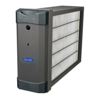
ERV & HRV: User and Installer Manual
Manufacturer reserves the right to change, at any time, specifications and designs without notice and without obligations.
11
UNIT INTERCONNECTION WITH CENTRAL
FORCED-AIR SYSTEM (R/C/G/G
F
)
NOTE: In this configuration, a separate ERV/HRV wall control is
required to operate the ventilator connected to the J9 terminal block. See
(CONNECTIONS on p8).
A210083
Fig. 18 – Wiring Options with Central Forced-Air System
These connections must be done if you want the unit to force the central
forced-air system blower operation when ventilating (see solid lines in
Fig. 18).
NOTE: These connections are required for installation configuration
T-4. Refer to (INSTALLING THE DUCTWORK AND THE
REGISTERS on p5) for more details.
SYNCHRONIZATION WITH CENTRAL
FORCED-AIR SYSTEM FUNCTION
The new ventilation technology allows synchronizing the unit operation
with the central forced-air system operating time. It prevents
unnecessary central forced-air system operating time while providing a
better air distribution.
To use this function, W and Y connections must be added to R and C
connections to inform the unit that the central forced-air system is
running (refer to dotted lines in Fig. 18).
Infinity®/Evolution™ Control
NOTE: Do not connect the Infinity® System Control directly to the
ventilator, as that may cause damage. If you have an Infinity® System
Control use one of the optional Main Wall Controls.
If you want the Infinity® System Control to control the ventilator, then
you must use a NIM (Network Interface Module) P/N SYSTXCCNIM01
and a Translator Board P/N SYSTXXXTRB01 in order for the System
Control to communicate properly. If using the Infinity® Zoning Panel
P/N SYSTXCC4ZC01 with the ventilators you must use the Translator
Board to communicate between the Zoning Panel and the ventilator
(Fig. 19). See the Translator Board Installation Instructions for NIM and
TRB requirements for newest ERV and HRV models. See the
Installation Manual for wiring diagrams.
Please do not connect the Network Interface Module (NIM) or the
Infinity® Zoning Panel to the two terminal blocks on the new ventilator.
The new ventilator terminals do not match up to the NIM or Infinity®
Zoning Panel terminals. Connecting the two controls may cause damage.
A210180
Fig. 19 – New Ventilator & NIM Connections
Central Forced-Air System Thermostat
J13
C
G
Vent
Gf
R
Y W G R C
R
Optional Wiring for Synchronization
Terminal Blocks
Air Exchanger PCB
Y
W
D
-
D+
GND
J9
OVR
LED
12V
A
B
C
D
B
G
R
Y
C
OVR
LED
12V
D-
D+
GND
12V
D-
D+
GND
W
O
Y1
R
Y2
A
B
C
D
B
G
R
Y
A
B
C
D
FUSE
YellowGreen
New ERV / HRV
Models
Translator Board
Furnace
System Wall
Control
Network Interface Module
(NIM)
Yellow G reen
OFF
A B C D
CLS1
COM1
OPN1
LAT COM HPT
Y R G B
ZS1
ZS1C
ZS2
ZS2C
ZS3
ZS3C
ZS4
ZS4C
CLS2
COM2
OPN2
CLS3
COM3
OPN3
CLS4
COM4
OPN4
Zone-1
Damper
Optional
Zone-1
Sensor
Zone-2
Sensor
Zone-3
Sensor
Zone-4
Sensor
Zoning User Interface &
Smart Sensor(s)
Connection
A B C D
Y R G B
Indoor
Unit
A B C D
A B C D
2-spd.
Outdoor
Unit
A B C D
Ventilator
Unit
Optional -
Leaving Air & Heat Pump
Temperature Sensor
See Note _
Zone-2
Damper
Zone-3
Damper
Zone-4
Damper
Status LEDs
DIP Switch
Damper Control Module, Zones 1 - 4
ABCD Connection:
A = Green: RS485+
B = Yellow: RS485-
C = White: 24VAC (COM)
D = Red: 24VAC (HOT)
Dampers:
CLS_ = Close
COM_ = Common
OPN_ = Open
F USE
1 2
ON
OVR
LED
12V
D-
D+
GND
12V
D-
D+
GND
B
G
R
Y
New ERV / HRV
Models
Translator Board
Zone Panel Control
 Loading...
