F80CTL and G80CTL: Installation, Start–Up, Operating and Service and Maintenance Instructions
Manufacturer reserves the right to change, at any time, specifications and designs without notice and without obligations.
10
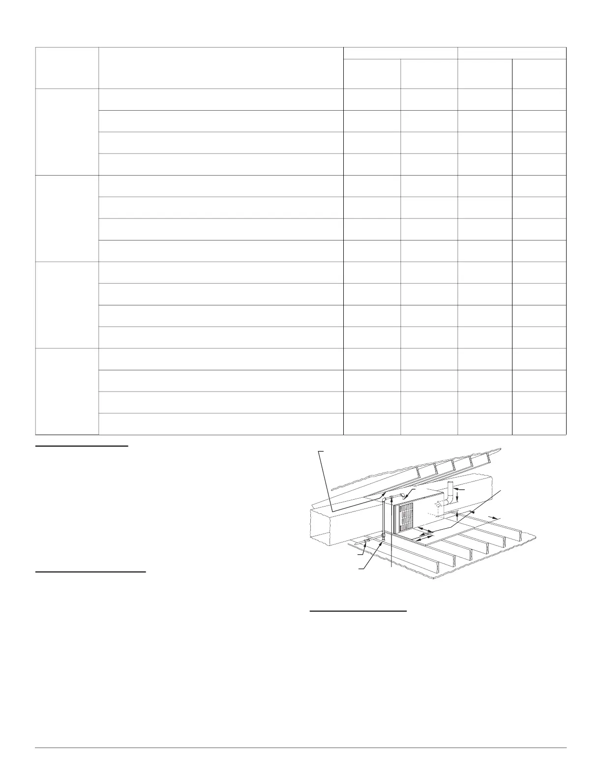
Roll-Out Protection
Provide a minimum 17-3/4-in. X 22-in. (451 X 559 mm) piece of sheet
metal for flame roll-out protection in front of burner area for furnaces
closer than 12-in. (305 mm) above the combustible deck or suspended
furnaces closer than 12-in. (305 mm) to joists. The sheet metal MUST
extend underneath the furnace casing by 1-in. (25 mm) with the door
removed.
The bottom closure panel on furnaces of widths 17-1/2-in. (445 mm) and
larger may be used for flame roll-out protection when bottom of furnace
is used for return air connection. See Fig. 13 for proper orientation of
roll-out shield.
Bottom Return Air Inlet
These furnaces are shipped with bottom closure panel installed in bottom
return-air opening. Remove and discard this panel when bottom return
air is used. To remove bottom closure panel, perform the following:
1. Tilt or raise furnace and remove two screws holding bottom filler
panel, see Fig. 9.
2. Rotate bottom filler panel downward to release holding tabs.
3. Remove bottom closure panel.
4. Reinstall bottom filler panel and screws.
A10164
Fig. 13 – Typical Attic Installation
Side Return Air Inlet
These furnaces are shipped with bottom closure panel installed in bottom
return-air opening. This panel MUST be in place when side return air
inlet(s) are used without a bottom return air inlet.
Not all horizontal furnaces are approved for side return air connections,
see Fig. 20.
Table 3 – Opening Dimensions - In. (mm)
FURNACE
CASING
WIDTH
IN. (mm)
APPLICATION
PLENUM OPENING FLOOR OPENING
A B C D
14–3/16
(360)
Upflow Applications on Combustible or Noncombustible
Flooring (subbase not required)
12-11/16
(322)
21-5/8
(549)
13-5/16
(338)
22-1/4
(565)
Downflow Applications on Noncombustible Flooring
(subbase not required)
12-9/16
(319)
19
(483)
13-3/16
(335)
19-5/8
(498)
Downflow applications on Combustible Flooring
(subbase required)
11-13/16
(284)
19
(483)
13-7/16
(341)
20-5/8
(600)
Downflow Applications on Combustible Flooring with coil assembly or coil
box (subbase not required)
12-5/16
(319)
19
(483)
13-5/16
(338)
20
(508)
17–1/2
(445)
Upflow Applications on Combustible or Noncombustible
Flooring (subbase not required)
16
(406)
21-5/8
(549)
16-5/8
(422)
22-1/4
(565)
Downflow Applications on Noncombustible Flooring
(subbase not required)
15-7/8
(403)
19
(483)
16-1/2
(419)
19-5/8
(498)
Downflow Applications on Combustible Flooring
(subbase required)
15-1/8
(384)
19
(483)
16-3/4
(425)
20-5/8
(600)
Downflow Applications on Combustible Flooring with coil assembly or coil
box (subbase not required)
15-1/2
(394)
19
(483)
16-1/2
(419)
20
(508)
21
(533)
Upflow Applications on Combustible or Noncombustible
Flooring (subbase not required)
19-1/2
(495)
21-5/8
(549)
20-1/8
(511)
22-1/4
(565)
Downflow Applications on Noncombustible Flooring
(subbase not required)
19-3/8
(492)
19
(483)
20
(508)
19-5/8
(498)
Downflow Applications on Combustible Flooring
(subbase required)
18-5/8
(473)
19
(483)
20-1/4
(514)
20-5/8
(600)
Downflow Applications on Combustible Flooring with coil assembly or coil
box (subbase not required)
19
(483)
19
(483)
20
(508)
20
(508)
24-1/2
(622)
Upflow Applications on Combustible or Noncombustible
Flooring (subbase not required)
23
(584)
21-1/8
(537)
23-5/8
(600)
22-1/4
(565)
Downflow Applications on Noncombustible Flooring
(subbase not required)
22-7/8
(581)
19
(483)
23-1/2
(597)
19-5/8
(498)
Downflow Applications on Combustible Flooring
(subbase required)
22-1/8
(562)
19
(483)
23-3/4
(603)
20-5/8
(600)
Downflow Applications on Combustible Flooring with coil assembly or coil
box (subbase not required)
22-1/2
(572)
19
(483)
23-1/2
(597)
20
(508)
30-IN. (762mm)
MIN WORK AREA
6″ MIN*
TYPE-B
VENT
17
3
/4
″
22
″
SHEET
METAL
SEDIMENT
TRAP
EQUIPMENT MANUAL
SHUT-OFF GAS VALVE
LINE CONTACT ONLY PERMISSIBLE BETWEEN
LINES FORMED BY INTERSECTIONS OF
THE TOP AND TWO SIDES OF THE FURNACE
JACKET AND BUILDING JOISTS,
STUDS, OR FRAMING.
GAS
ENTRY
17
3
/4
″
(451mm)
OVERALL
4
3
/4
″
(121mm)
UNDER DOOR
1″
(25mm)
UNDER FURNACE
EXTEND OUT 12″
(305mm)
FROM FACE OF DOOR
* WHEN USED WITH
SINGLE WALL VENT
CONNECTIONS
UNION
(152mm)
(451mm)
(559mm)