10
FILTER
ACCESS
PANEL
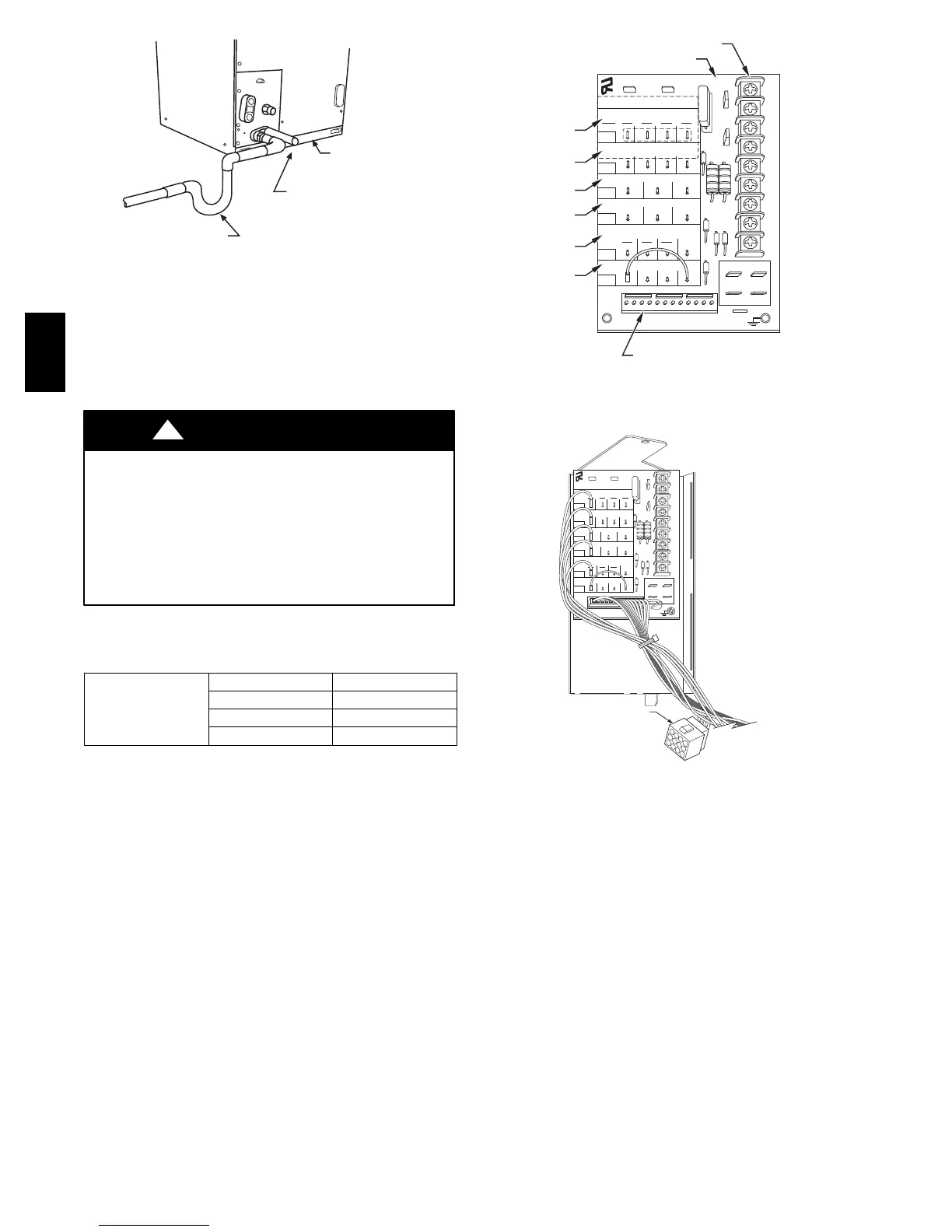
SECONDARY DRAIN WITH
APPROPRIATE TRAP REQUIRED
(USE FACTORY KIT OR
FIELD-SUPPLIED TRAP)
PRIMARY TRAP REQUIRED
(USE FACTORY KIT OR
FIELD-SUPPLIED TRAP OF
SUFFICIENT DEPTH.
STANDARD P-TRAPS ARE
NOT SUFFICIENT. SEE
FIGURE OF RECOMMENDED
CONDENSATE TRAP)
A03003
Fig. 16 -- Insufficient Condensate Trap
Condensate drain lines should be pitched downward at a minimum
of 1 in. (25mm) for every 10 ft. (3m) of length. Consult local codes
for additional restrictions or precautions.
UNIT COMPONENT HAZARD
Failure to follow this caution may result in product damage.
Never operate unit without a filter. Damage to blower motor
or coil may result. Factory authorized filter kits must be used
when locating the filter inside the unit. For those applications
where access to an internal filter is impractical, a
field--supplied filter must be installed in the return duct
system.
CAUTION
!
IMPORTANT: Factory authorized filters must be used when
locating the filter inside the unit. (See Table 1.)
Table1–FilterKits
FILTER KIT (12
PACK)
PART NUMBER SIZE USED WITH
KFAFK0212MED 002
KFAFK0312LRG 003, 005
KFAFK0412XXL 006
Pr ocedure 7 — UNIT STAR T--UP
Refer to outdoor unit Installation Instructions for system start--up
instructions and refrigerant charging method details.
Procedure 8 — EASY SELECT
CONFIGURATION TAPS
Easy Selectt taps are used by the installer to configure a system.
The ECM motor uses the selected taps to modify its operation to a
pre--programmed table of airflows. (See Table 3 and 4.) Airflows
are based on system size or mode of operation and those airflows
are modified in response to other inputs such as the need for
de-- humidification. (See Fig. 17 and 18.)
EASY SELECT
D
H
R
W
1
W
2
Y
1
Y/ Y
2
G
O
C
HEATER/MOTOR
CEBD430226-01B CESS430226-01B
AUX HEAT KW/CFM
0-20
1100
SEC1 SEC2
J1
J2
AC/HP SIZE
036 030 024 018
AC
HP-COMFORT
HP-EFF
NOM HI
ENH
LO
SYSTEM TYPE
AC/HP CFM ADJUST
ON/OFF DELAY
CONTINUOUS FAN
MED HI YELLO
AUX1 HUM1
AUX2
24VAC
GRY
HUM2
YEL
WHT
BLK
ORN
BLU
VIO
0-15
875
0-10
675
0
90
30
90
0
0
0-5
625
TM
A
B
C
D
E
F
KW
CFM
LOW VOLTAGE TERMINAL BLOCK
PRINTED CIRCUIT BOARD
MOLEX 12-PIN CONNECTOR
A95275
Fig. 17 -- Detail of FV4C Printed --Circuit Board
EASY SELECT
D
H
R
W
1
W
2
Y
1
Y/ Y
2
G
O
C
HEATER/MOTOR
CEBD430226-01B CESS430226-01B
AUX HEAT KW/CFM
0-30
1075
SEC1 SEC2
J1
J2
AC/HP SIZE
036 030 024 018
AC
HP-COMFORT
HP-EFF
NOM HI
ENH
LO
SYSTEM TYPE
AC/HP CFM ADJUST
ON/OFF DELAY
CONTINUOUS FAN
MED HI YELLO
AUX1 HUM1
AUX2
24VAC
GRY
HUM2
YEL
WHT
BLK
ORN
BLU
VIO
0-20
875
0-10
725
0
90
30
90
0
0
0-5
625
TM
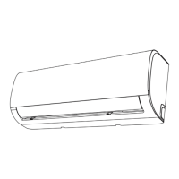
12-PIN MATE-N-LOCK
ELECTRIC HEAT CONNECTOR
A95276
Fig. 18 -- Detail of FV4C Printed --Circuit Board
The FV4C Fan Coil must be configured to operate properly with
system components with which it is installed. To successfully
configure a basic system (see information printed on circuit board
label located next to select pins), move the 6 select wires to the pins
which match the components used.
A. AUX HEAT KW/CFM -- Select heater range for size of
electric heater installed
Installer must select the auxiliary heat airflow approved for
application with kW size heater installed. If no heater is installed,
this step can be skipped. Each select pin is marked with a range of
heaters for which airflow, also marked, is approved. For increased
comfort select the narrowest kW range matching the heater size, for
example, 0--10 for 10--kW heater. This airflow must be greater than
the minimum CFM for electric heater application with the size
system installed for safe and continuous operation. (See Table 5
and 6 for airflow delivery and minimum CFM.) Note that airflow
marked is the airflow which will be supplied in emer gency heat
mode and heating mode on air conditioners when electric heat is
the primary heating source. In heat pump heating mode when
electric heaters are energized, the ECM motor will run the higher of
heat pump heating airflow and electric heater airflow to ensure safe
FV4C