24VNA6 / 25VNA4: Service Manual
Manufacturer reserves the right to change, at any time, specifications and designs without notice and without obligations.
6
Control Connection (Communicating and
Non-Communicating)
The primary system control interface for the PCM is the communicating
Infinity Control. The PCM also supports traditional 24VAC discrete
control signals in an emergency mode of operation when a
communicating control is not available.
Communicating Infinity Control
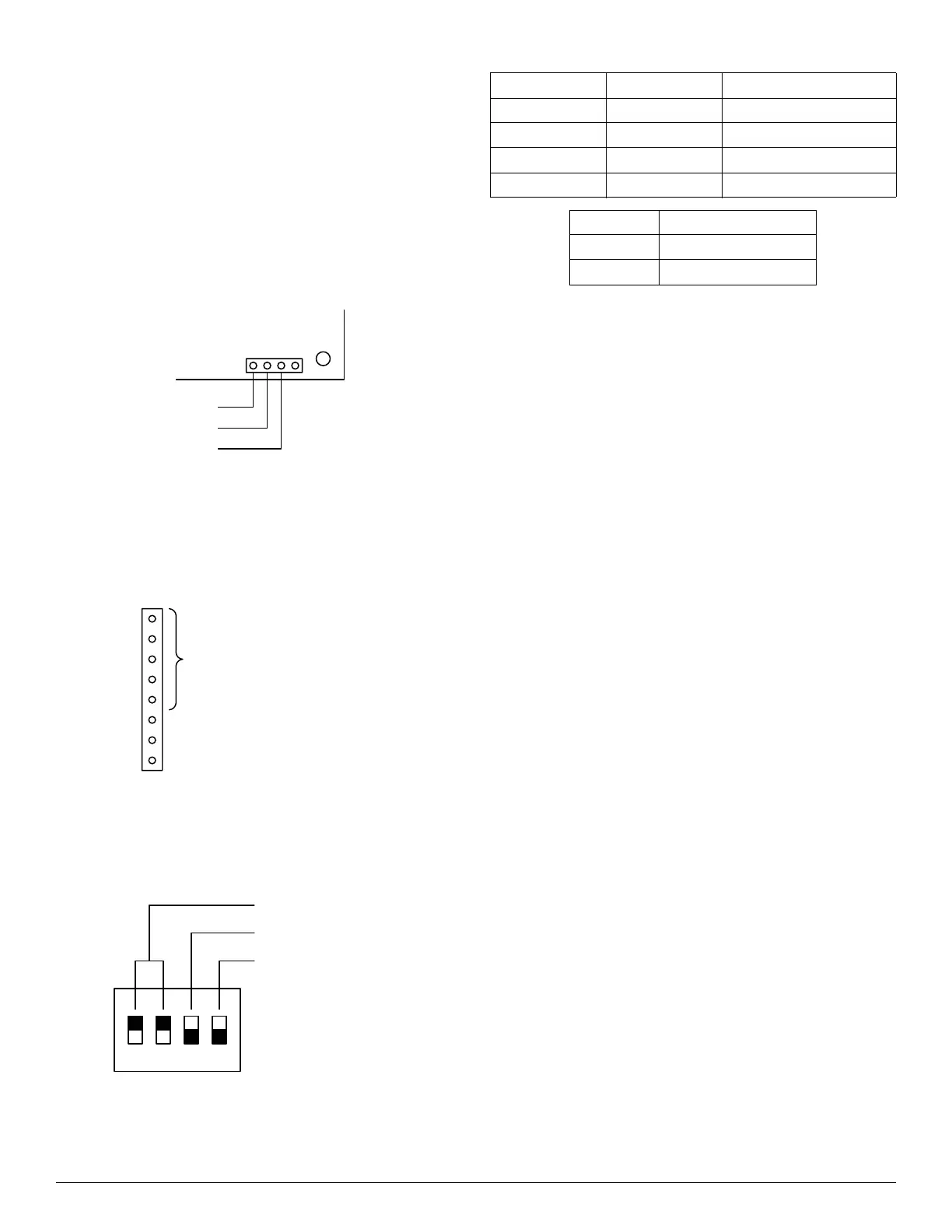
The communicating Infinity Control uses a 2-wire connection as shown
in Fig. 3 and Fig. 4. An optional 3rd wire can be added for a ground
connection. The third wire is recommended for long communication
runs or if there are problems encountered with consistent communication
using a 2-wire setup. The Comm light indicates whether communication
is being received from a system control.
A200239
Fig. 4 – Infinity Control Connection
Non-Communicating Control
The non-communicating control connections are shown in Fig. 5.
Specific connections depend on system configuration. Note that O and
W are driven during Defrost for heat pump models.
A200240
Fig. 5 – Non-Communicating Control Connection
In non-communicating mode, the Performance Mode and Defrost
Interval are set using DIP switches. Switch assignments are shown in
Fig. 6. Switch settings are shown in the Table 1
A200241
Fig. 6 – Non-Communicating DIP Switch Assignment
Table 1 – DIP Swtich Settings
IMPORTANT: The R (Rc) signal on the PCM comes from the
transformer in the equipment. The phase of this transformer connection
is not controlled relative to the phase of the transformer in the indoor
equipment (Rh). Wiring requirements in this manual do not connect Rc
and Rh together. For any non-standard wiring, care should be taken to
make sure that Rc and Rh are not connected together. Doing so may
result in destroying one or both of the transformers in this and the
internal equipment.
PCM Indicators and Matrix Display
The PCM contains three indicator lights (LEDs) and a dot matrix
display. Indicator and display location is shown in Fig. 7. The
indicators are described briefly below. Indicator operation and
interpretation is described in the Control Features section.
Status Light
The status light is a single color amber LED that indicates equipment
operating status and diagnostic conditions.
Comm Light
The Comm light is a single color green LED that indicates the
communication state and system control state of the equipment.
VFD Comm Light
The VFD Comm Light is a bi-color red / green LED that indicates the
communication with the VFD.
Matrix Display
The matrix display is a 5x7 dot matrix for displaying messages and
diagnostic information.
NON-COMMUNICATING
CONTROL CONNECTIONS
NOTE: O should be active in Cooling
Performance Mode
Defrost Interval
4321
ON
Switch 1 Switch 2 Defrost Interval
Up Up Auto
Up Down 30 minutes
Down Up 60 minutes
Down Down 90 minutes
Switch 3 Performance Mode
Up Efficiency
Down Comfort
 Loading...