24VNA6 / 25VNA4: Service Manual
Manufacturer reserves the right to change, at any time, specifications and designs without notice and without obligations.
8
Model Plug
Each control board contains a model plug. The model plug is used to
identify the type and size of equipment to the PCM.
Thermistors
The equipment contains 4 thermistors as described below.
• Outdoor Ambient Temperature (OAT)
• Outdoor Coil Temperature (OCT)
• Outdoor Suction Temperature (OST)
• Outdoor Discharge Temperature (ODT)
Pressure Sensors
The equipment contains two pressure transducers:
• Suction Pressure Transducer (SPT)
• Discharge Pressure Transducer (DPT)
The two transducers are identical parts installed on the suction inlet to
the compressor and discharge outlet of the compressor respectively. The
transducers have a sensing range of 0 to 620 psig. The connection points
to the PCM are labeled P1 and P2. These two connection points are
identical. Either pressure transducer can connected to either input. The
software in the PCM detects which transducer is connected to which
input and assigns the signals accordingly.
VFD Control Connection
The VFD Control Connection consists of 6 wires as shown in Fig. 3.
Two of the wires provide a control enable signal. Four of the wires are
used for communication between the PCM and the VFD.
Pressure Equalization Valve (PEV)
The PEV is actuated by a 24VAC control solenoid. The PCM controls
the PEV by providing a drive signal to the PEV control solenoid. The
PEV is used to reduce the pressure differential between the compressor
suction and discharge ports.
Reversing Valve (RVS)
(25VNA4 Only)
The RVS is actuated by a 24VAC control solenoid. The PCM controls
the RVS by providing a drive signal to the RVS control solenoid. The
RVS is used to reverse refrigerant flow between the Cooling and Heating
modes in a heat pump. AC equipment does not contain an RVS. The
RVS will be energized during Cooling operation and during the Defrost
mode in Heating operation.
Heating Electronic Expansion Valve (EXV-H)
(25VNA4 Only)
The EXV-H is an electronically controlled needle valve for regulating
refrigerant flow during heating operation. The EXV-H is driven by a
12VDC, 2-phase, uni-polar stepper motor. The EXV-H has a 475 step
range between fully closed and fully open. The PCM drives the EXV at a
rate of 77 steps per second. The PCM initializes the EXV-H to the
closed position when power is applied to the equipment. This process
takes approximately 7 seconds.
When the compressor is not running, the EXV-H is closed. When
operating in Cooling or in Defrost mode of heating, the EXV-H will be
fully open. When operating in Heating mode, the EXV-H is actively
controlled to maintain suction super heat to the control target value.
Bluetooth® Module
The Bluetooth Module is a wireless service communication device
allowing the equipment to communicate with the Carrier Service Tech
App. The Carrier Service Tech App can be used to retrieve diagnostic
information, equipment operating history, and reprogram the PCM or the
VFD.
Accessory Control Components
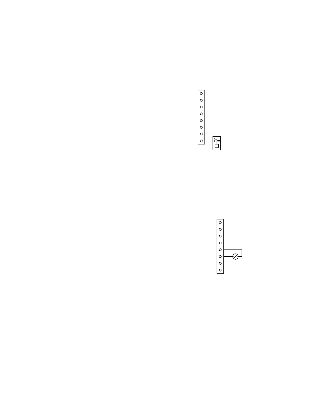
Utility Curtailment
The Utility Curtailment feature is controlled by an optional external
switch or relay wired to the two UTIL connections on the PCM as shown
in Fig. 8. The UTIL connections are wired to the normally open switch
contacts. This input allows a power utility device to interrupt equipment
operation during peak load periods. When the utility sends a signal to
shut the system down, the equipment sends a curtailment indication to
the Infinity Control. The Infinity Control will command an equipment
shutdown and may display a curtailment notification. See Infinity
Control installation or service instructions for more detail.
A200242
Fig. 8 – Curtailment Switch/Relay Connection
Liquid Line Solenoid Valve (LLS)
The LLS is an optional external normally closed valve that is installed in
systems with large vertical distance offsets between the indoor
equipment and outdoor equipment. The outdoor equipment will
energize the valve when the compressor is running, and de-energize the
valve when the compressor is not running to prevent gravity-induced
migration of liquid refrigerant. The LLS is wired between the C and
LLS contacts as shown in Fig. 9.
A200243
Fig. 9 – Curtailment Switch / Relay Connection (LLS)
O
UTIL
LLS
 Loading...