25VNA4: Installation Instructions
Manufacturer reserves the right to change, at any time, specifications and designs without notice and without obligations.
16
Troubleshooting
Systems Communication Failure
If communication with the Infinity control is lost with the User Interface
(UI), the control will flash the appropriate fault code (see Table 8).
Check the wiring to the User Interface and the indoor and outdoor units
and power.
Model Plug
Each control board contains a model plug. The correct model plug must
be installed for the system to operate properly (see Table 4).
The model plug is used to identify the type and size of unit to the control.
On new units, the model and serial numbers are input into the board’s
memory at the factory. If a model plug is lost or missing at initial
installation, the unit will operate according to the information input at
the factory and the appropriate error code will flash temporarily. An RC
replacement board contains no model and serial information. If the
factory control board fails, the model plug must be transferred from the
original board to the replacement board for the unit to operate.
NOTE: The model plug takes priority over factory model information
input at the factory. If the model plug is removed after initial power up,
the unit will operate according to the last valid model plug installed, and
flash the appropriate fault code temporarily.
Pressure Switch Protection
The outdoor unit is equipped with high pressure switch. If this switch
opens the VFD will lose line power and the compressor and fan motor
will not operate. The high pressure switch opens at 670 +/- 10 psig and
closes at 470 +/- 25 psig. If this occurs the PCM will set a diagnostic
code per table 7. The outdoor pressure transducer installed at the
discharge of the compressor is monitored by the PCM and the PCM will
take action to avoid the high pressure switch from opening.
Compressor Protection
The Primary Control Module continuously monitors the operation of the
compressor and takes action when it is nearing the edge of the
boundaries of reliable operation. The PCM utilizes the pressure
transducers to maximize the reliability and minimize the off time of the
system due to operation outside of the compressor boundaries. The
PCM takes different actions for each edge of the boundary, but each
culminates in a reduction of compressor speed to the minimum
allowable and, in the worst case, will power off the compressor to avoid
excursions outside the boundaries. If a shutdown does occur then the
PCM will set a diagnostic code per Table 8.
Line Voltage Diagnostics
The primary control module monitors the line voltage for low and high
voltage events. If a low voltage or high voltage event occurs and another
fault occurs simultaneously the PCM will set a fault that indicates this
was due to the system conditions and not the components. If this occurs
several times in a row the PCM will set a malfunction and lock out
operation for 1-4 hours, depending on the condition. Refer to Table 8 for
the list of fault codes and Table 9 for the list of malfunctions and the
lockout times for each one.
Forced Defrost Pins (J9)
The forced defrost pins have several functions. When shorting the pins
using a clip wire the below functions can be executed:
"If the pins are shorted for more than 5 seconds and the unit is in heating
mode then the unit will enter into a defrost.
"If the pins are shorted more than 1 seconds and less than 5 seconds
when the system has just turned off and an active call for cooling or
heating is present the 5 minute initial on-time will be defeated.
"If the unit is in the OFF mode and the pins are shorted at power on the
unit will enter into Status Code Recall Mode.
Temperature Thermistors
Thermistors are electronic devices which sense temperature. As the
temperature increases, the resistance decreases. Thermistors are used to
sense outdoor air (OAT), coil temperature (OCT), the suction line
thermistor (OST) between the reversing valve and the accumulator, and
the outdoor discharge thermistor (ODT) at the outlet from the
compressor.
Refer to Table 5 and Table 6 for resistance values versus temperature for
the OAT, OCT, and OST.
If the outdoor air or coil thermistor should fail, the control will flash the
appropriate fault code (see Table 8.)
IMPORTANT: The outdoor air thermistor, coil thermistor and suction
thermistor should be factory mounted in the final locations. Check to
ensure thermistors are mounted properly (See Fig. 29, Fig. 30 and
Fig. 31).
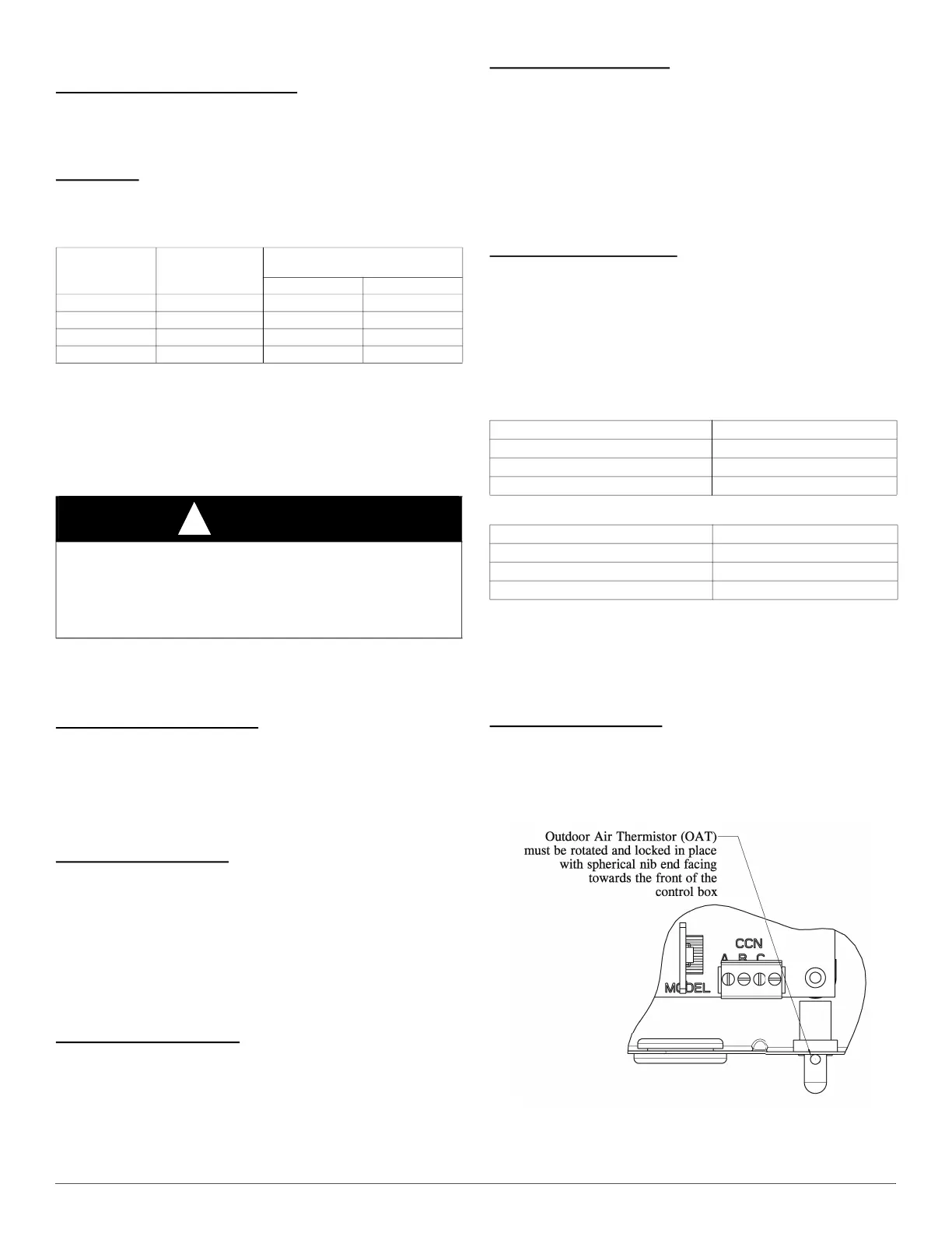
Outdoor Air Thermistor
The outdoor air thermistor is a 10Kohm resistor used for multiple system
operations. It provides the outdoor air temperature to the primary
control module and user interface. It is essential for controlling the
system and is used in almost all modes of operation. The sensor is
mounted in the control box per Fig. 29.
A200045
Fig. 29 – Outdoor Air Thermistor Mounting Location
Table 4 – Model Plug Information
MODEL
NUMBER
MODEL PLUG
NUMBER
PIN RESISTANCE
(K-ohms)
Pins 1-4 Pins 2-3
25VNA424 HK70EZ003 5.1K 24K
25VNA436 HK70EZ015 5.1K 360K
25VNA448 HK70EZ027 11K 150K
25VNA460 HK70EZ039 18K 62K
CAUTION
!
EQUIPMENT DAMAGE HAZARD
Failure to follow this caution may result in equipment damage and/or
improper operation.
Do not attempt to install an incorrect model plug as this could cause
some units to operate incorrectly and fail prematurely.
Table 5 – Resistance Values versus Temperature
TEMPERATURE RESISTANCE (ohms)
25.0°C (77.0°F) 10.0 + / - 2.3%
0.0°C (32.0°F) 32.6 + / - 3.2%
-17.8°C (0 °F) 85.5 + / - 3.4%
Table 6 – ODT Resistance Values versus Temperatures
TEMPERATURE (°C) RESISTANCE (K OHMS)
25 50.15 + / - 5.0%
75 7.565 + / - 3.0%
125 1.7 + / - 1.4%

 Loading...