Variable-Speed
Furnace/Fan Coil
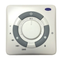
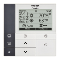
User Interface
i
] GEeen
] YelFOW
] White
] Red
op ono,R.......
[]# Rooms...... f_°
Humidifier HUM
ConnecEon_ -- "0'
7#
ABCD
Connection
1-Spd. AC
yh'2 Y
OAT_= _ SOATo
ii, _ r
typical example for a communicating Variable-Speed Furnace .
Fan Coil with a 2-spd. Air Conditioner Heat Pump (including
Dual Fuel).
The User Interface display will light up and indicate that it is now
"ESTABLISHING COMMUNICATIONS WITH EQUIPMENT
PLEASE WAIT". The User Interface will automatically continue
by "SEARCHING FOR INDOOR EQUIPMENT", followed by
"SEARCHING FOR OUTDOOR EQUIPMENT" (See Figure 15).
Once the indoor and outdoor equipment has been found, the
Installer will be asked to select Accessories. Proceed to Section 4.
Selecting Accessories.
NOTE: If the variable-speed indoor equipment (furnace or fan
coil) cannot be found, the User Interface will display "CANNOT
COMMUNICATE WITH INDOOR UNIT". This MUST be
con'ected before the initial power up sequence can continue. If
indoor unit is found, but the outdoor unit is not found, "OUT-
DOOR UNIT NOT IDENTIFIED" will appear. Proceed to the next
section Ibr Outdoor Unit Identification.
Fig. 13--Connection Diagram for
Furnace or FE Fan Coil w/1-Spd. AC
A03147
User Interface
[]
[]
[]
[]
[]
[]
Green
Y_l_ow
White
Red
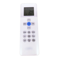
OptionN Remote
Room Sensor
1-Spd. HP
"0 c
R g" "OR
o• "Qo
w • "•w2
y• "•y
Variable-Speed
Fan Coil
OAT
• "_ _ SeRsor
Fig. 14_Connection Diagram for
FE Fan Coil w/1-Spd. HP
A03148
ll'.tl k'JI:IFF/I]I[']
FIRE OR EQUIPMENT HAZARD
Failure to follow this waming could result in equipment
damage or fire.
Do not apply 24vac fan powered humidifier (with internal
power supply) direct to indoor unit HUM and COM termi-
nals.
INITIAL POWER-UP
NOTE: Refer to Functional Ovmwiew (Fig. 11) to become
familiar with key fi.mction buttons such as "System On/Off",
'Tan", "Left-Side" and "Right-Side" buttons, etc. These function
buttons will be used frequently during setup.
SECTION 1 POWER UP SEQUENCE
This secnon ad&esses initial power up (or commissioning) of a
new Infinity ContFo1TM. The User Interface will communicate and
identify all Infinity components in the system. The following is a
ESTABLISHING
COMMUNICATIONS
WITH EQUIPMENT
PLEASE WAIT
SOFTWARE
VERSION
INDOOR UNIT
SEARCHING FOR
INDOOR EQUIPMENT
WORKING
OUTDOOR UNIT
SEARCHING FOR
OUTDOOR EQUIPMENT
WORKING
A03195
Fig. 15 -- Power Up Sequence
SECTION 2 SELECTING OUTDOOR UNIT
If there is no communicating outdoor unit, the screen, shown in
Fig. 16, will appear. Press either Time or Temp +/- buttons to
select AC (air conditioner), HP (heat pump), or None (no unit
installed). Press the right-side button to continue to the next screen.
If you have selected either AC or HP as the outdoor unit type, the
following middle screen will appear (See figure 16). Press either
Time or Temp +/- buttons to select appropriate Btu size of outdoor
unit, then press right side button to continue. If a NIM (Network
Interface Module) is applied for non-communicating two-speed
outdoor equipment, select 1 or 2speed compressor operation, and
press right-side button to continue.
NOTE: Range of Btu selection is limited by the model number of
the indoor unit installed. The Infinity Control TM will not allow an
outdoor unit size that is not supported by the installed indoor unit.
OUTDOOR UNIT
NOT IDENTIFIED
SELECT TYPE:
NONE, AC, HP
PRESS +/-TO MAKE
SELECTION
CONTINUE>
OUTDOOR UNIT
ENTER HEAT PUMP
SiZE Igrffff_lrffi-irU
18000 TO 60000 BTU
PRESS +/- TO MAKE
SELECTION
< SACK CONTINUE >
OUTDOOR UNiT
HEAT PUMP
ENTER NUMBER OF
SPEEDS, 1 or 2: []
PRESS +E TO MAKE
SELECTION
< BACK CONTINUE >
AU319
Fig. 16_Selecting Outdoor Unit
NOTE: On new system installations, the model and serial number
will be recognized and displayed. On any indoor_outdoor board
replacements, the equipment will be recognized but the exact
model/serial number will not be displayed.
SECTION 3 SELECTING ELECTRIC HEATER
If the indoor unit is a fan coil and the electric heater is not
self-identifying, "ELECTRIC HEATER NOT IDENTIFIED" will
appear (See figure 17). Press either Time or Temp +/- buttons to
select appropriate size of electFic heater installed, then press the
right-side button to continue.
 Loading...