EasyManua.ls Logo

Carrier Infinity Control SYSTXCCUID01 User Manual

Carrier Infinity Control SYSTXCCUID01
12 pages
To Next Page IconTo Next Page
Page #1 background imageLoading...
Page #1 background image
HEATING & COOUNG
Visit www.carrier.cmn
SYSTXCCUID01
Infinity Control TM
Installation and Start-Up Instructions
Infinity Control TM
SYSTXCCUID01
A03149
NOTE: Read the entire instruction manual before starting the
installation.
This symbol =-> indicates a change since the last issue.
TABLE OF CONTENTS
SAFETY CONSIDERATIONS ..................................................... 1
INTRODUCTION .......................................................................... 1
INSTALLATION AND START-UP OVERVIEW ...................... 1
INSTALLATION ........................................................................... 2
INITIAL POWER-UP .................................................................... 5
QUICK START .............................................................................. 6
INSTALL / SERVICE MENUS .................................................... 7
OPERATIONAL INFORMATION ............................................. 11
TROUBLESHOOTING ............................................................... 12
SAFETY CONSIDERATIONS
Read and follow manufacturer instructions carefully. Follow all
local electrical codes during installation. All wiring must conform
to local and national electrical codes, hnproper wiring or installa-
tion may damage Infinity Control System. Recognize safety
information. This is the safety-alert symbol Z_x When you see this
symbol on the equipment and in the instruction manual, be alert to
the potential for personal injury. Understand the signal words
DANGER, WARNING, and CAIfTION.
These words are used with the safety-alert symbol. DANGER
identifies the most serious hazards, which will result in severe
personal injury or death. WARNING signifies a hazard, which
could result in personal injury or death. CAUTION is used to
identify unsafe practices, which would result in minor personal
injury or product and property damage. NOTE is used to highlight
suggestions which will result in enhanced installation, reliability,
or operation.
INTRODUCTION
The Infinity System consists of intelligent communicating com-
ponents (User Interface, variable speed furnace or fan coil, AC or
HP), which continually communicate with each other via a
four-wire connection called the ABCD bus. Conventional 24-volt
signals on dedicated wires are not needed. Commands, operating
conditions, and other data are passed continually between the
components over the ABCD bus. The result is a new level of
comlbrt, versatility, and simplicity.
An Infinity System consists of a Infinity Control TM (themmstat
plus much more) and an Infinity furnace or fan coil. All Infinity
furnaces or ban coils are variable-speed and nmlti stage for
maximum flexibility, efficiency, and comlbrt. They support con-
trolled ventilation, humidification, dehumidification, and air qual-
ity control. Either an Infinity dual capacity (communicating), or a
standard 24 vac controlled outdoor unit may be used.
When using conventional outdoor units, the Infinity furnace or fan
coil provides the 24 volt signals needed to control them. Also, the
Infinity Network Interface Module (NIM) allows connection of a
conventional HRV or ERV without the need for a separate wall
control.
All system components are controlled through the wall mounted
Infinity Control TM, which replaces the conventional thermostat and
provides the homeowner with a single wall control for all the
features of the system.
INSTALLATION AND START-UP OVERVIEW
This instruction covers installation of the Infinity Control TM only.
Physical installation instructions for the indoor, outdoor equipment
and accessories are provided with each unit.
Setup, commissioning, operation, and troubleshooting of the
Infinity System is covered only in this installation instruction. It is
your guide to connecting the system components and commission-
ing the system once all the physical components are installed.
Special screen prompts and start-up capabilities are provided in the
Infinity System to simplify and lead you through the initial
connnissioning of the system. So:
Install the Infinity ControV M according to this instruction.
Install the indoor unit, outdoor unit, and accessories according
to their instructions.
Wire the complete system according to this instruction.
Setup, commission, and operate the system according to this
instruction to assure yourself a smooth and trouble free
start-up.
Manufacturer reserves the right to discontinue, or change at any time, specifications or designs without notice and without incurring obligations.
_m PC 101 Catalog No 809-50020 Printed in USA. Form UID01-1Sl Pg 1 01-04 Replaces: NEW
isc
Question and Answer IconNeed help?

Do you have a question about the Carrier Infinity Control SYSTXCCUID01 and is the answer not in the manual?

Carrier Infinity Control SYSTXCCUID01 Specifications

General IconGeneral
DisplayColor Touchscreen
CompatibilityCarrier Infinity System
Humidity ControlYes
ZoningSupports up to 8 zones
ConnectivityWired
Power Source24VAC
FeaturesRemote Access

Summary

Safety Considerations

Safety-Alert Symbol and Signal Words

Explains DANGER, WARNING, and CAUTION signal words used with the safety-alert symbol.

General Safety Instructions

Emphasizes following manufacturer instructions and local electrical codes for safe installation.

Introduction

Infinity System Overview

Describes the Infinity System's communicating components and benefits of variable-speed technology.

System Control

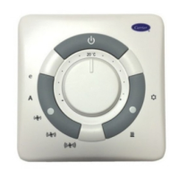
Explains how the Infinity Control acts as a central controller for all system features.

Installation and Start-Up Overview

Scope of Instructions

This document covers Infinity Control installation, setup, and commissioning.

Installation Process Steps

Outlines steps: install control, indoor/outdoor units, wire system, and commission.

Installation

Infinity Control Location and Wiring

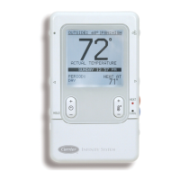
Guidelines for optimal placement and wiring of the Infinity Control unit.

Mounting the Infinity Control

Details on recess or surface mounting the Infinity Control, including decorative backplates.

Connecting the Wiring

Routing wires through the mounting plastic and connecting them to the terminal backplate.

Equipment Wiring Diagrams

Reference to diagrams for connecting the Infinity System components and accessories.

Humidifier Connection

Instructions for connecting bypass or fan-powered humidifiers to the system.

Initial Power-Up

Power Up Sequence

Describes the initial startup process for the Infinity Control, including equipment identification.

Selecting Outdoor Unit

Procedure to select the outdoor unit type (AC/HP) and Btu size during initial setup.

Selecting Electric Heater

Procedure to select the electric heater size if it's not self-identifying.

Selecting Accessories

Filter Type Selection

Options for selecting air filter type (Media, EAC) and setting the cleaning interval.

Humidifier and UV Lights Installation

Steps to indicate if a humidifier or UV lights are installed and set their maintenance intervals.

Equipment Summary and Setup Complete

Equipment Summary Screen

Displays a summary of all automatically found or manually selected system equipment.

Saving Selections

Confirms and saves all selected equipment and accessory settings to complete the initial setup.

Quick Start

Setting Day, Time, and Humidity

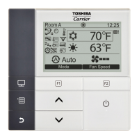
Guides on setting the current day, time, and desired humidity levels for the system.

Override Heating Schedule

Instructions on how to temporarily override the heating schedule and set a desired temperature.

Override Cooling Schedule

Instructions on how to temporarily override the cooling schedule and set a desired temperature.

Quick Program Schedule for All Days

Provides a quick guide to setting a uniform schedule for all days of the week.

Install/Service Menus

Accessing Install/Service Menus

Procedure to enter the Install/Service menus by holding the ADVANCED button.

Install/Service Menu Options

Overview of options: Equipment Summary, Install, Setup, Checkout, Service, Software Version.

Equipment Summary Menu

Displays recognized indoor/outdoor unit types, filter type, and installed accessories.

Install Menu

Initiates the start-up process to learn all system equipment.

Setup Menu

Setup - Thermostat

Configuration for Auto Mode, Deadband, Offsets, Cycles Per Hour, Programming, and Display.

Setup - Furnace

Configuration for Airflow, Heat Rise, Staging, Off Delay, and Lockout Temperature.

Setup - Fan Coil

Configuration for HP/AC Airflow, Dehumidify Airflow, and Heater Size.

Setup - Heat Pump / AC

Configuration for Cooling Lockout, Entered Size, Defrost Interval, and Electric Heat Lockout.

Setup - Accessories

Configuration for Filter Type, Humidifier, Ventilator, and UV Lights.

Setup - System Maintenance

Sets the interval for the normal System Maintenance notification for the homeowner.

Checkout Menus

Checkout - Furnace

Allows exercising of the furnace for low and high heat runtimes and ignition sequence.

Checkout - Fan Coil

Allows exercising of electric heat stages for fan coil units.

Checkout - Heat Pump Heating

Allows exercising of heat pump heating with selectable low/high runtimes and defrost cycle.

Checkout - Heat Pump Cooling or AC Cooling

Allows exercising of heat pump/AC cooling with selectable low/high runtimes.

Checkout - Humidifier

Allows exercising the humidifier to be turned On or Off.

Checkout - Ventilator

Allows exercising the ventilator through all of its operating speeds.

Service Info Menus

Service - Furnace Status

Displays current operating parameters like heat stage, airflow CFM, inducer/blower RPM, static pressure.

Service - Fan Coil Status

Displays current operating parameters for fan coil electric heat status and airflow.

Service - Heat Pump / AC Status

Displays status of heat pump/AC heating/cooling, defrost, airflow, coil temp, and static pressure.

Service - Last 10 System Faults

Shows the last 10 system faults, including time, date, and equipment identifier.

Service - Run / Fault History

Provides histories for indoor/outdoor units: fault counters, cycle counters, and lifetime run times.

Service - Today's Date

Allows entering the current date for time/date stamping of system faults.

Service - Model / Serial Numbers

Displays model and serial numbers of communicating equipment in the system.

Service - Service Phone Number

Enables entering contact information for homeowner service reminders.

Operational Information

Continuous Fan Operation

Explains how to use the FAN button to cycle through AUTO, LOW, MED, and HIGH fan speeds.

Five-Minute Compressor Timeguard

Details the compressor protection timer and how to temporarily defeat it.

Emergency Heat

Instructions on how to activate Emergency Heat by pressing and holding the HEAT button.

Keypad Lockout

Describes how to lock and unlock the keypad by pressing specific button combinations.

Heat and Cool LEDs

Notes that the Heat and Cool LEDs will pulsate during actual equipment operation.

Equipment Cycle Timer

Explains the timer preventing short cycling, adjustable from 4-6 cycles per hour.

Ten-Minute Staging Timer

Describes the timer preventing higher stages from activating until the previous stage runs for 10 minutes.

Three-Minute Minimum On Time

Notes that stages will remain on for a minimum of three minutes during normal operation.

Heat/Cool Set points

Explains the enforced minimum difference between heating and cooling set points.

Auto Changeover

Details the auto mode changeover time setting, adjustable from 5 to 120 minutes.

Smart Recovery

Describes how Smart Recovery adjusts room temperature before scheduled recovery times.

Troubleshooting

Infinity Control Not Powering Up

Troubleshooting steps for power issues, including checking wiring and fuses.

Indoor Unit Not Found

Steps to resolve 'Indoor Unit Not Found' error, checking wiring and connections.

Outdoor Unit Not Found

Troubleshooting steps for 'Outdoor Unit Not Found' error with two-speed units.

Returning to Start-Up Mode

Instructions on how to restart the system's initial setup process.

Critical Alert Screen Errors

Lists errors causing a Critical Malfunction screen and their potential causes.

System Malfunction Screen Errors

Lists errors causing a System Malfunction screen and their potential causes.

Related product manuals