KFFEH: Installation Instructions
Manufacturer reserves the right to change, at any time, specifications and designs without notice and without obligations.
2
NOTE: Use an accessory downflow base to maintain proper clearance
on downflow installations.
This instruction describes the installation of Part No. KFFEH accessory
heaters in FJ4 and PF4MNX fan coils.
Procedure 1 — Install Electric Heater Assembly
NOTE: Ensure heater coils are not deformed or damaged during heater
installation.
1. Make sure power to unit is off.
2. Remove blower access panel of fan coil unit.
3. Disconnect 2 power wires (black and yellow pigtail leads) from
PCB or wire harness (if applicable) and discard. Wires may be part
of a plug assembly or attached to terminals L1 and L2. Remove
cooling control plate from fan coil (if equipped). For 18-, 24-, and
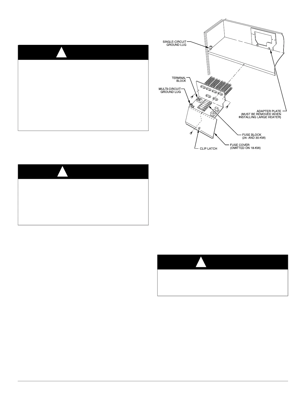
30-kW heaters, remove adapter plate (Fig. 1).
A90154
Fig. 1 – Installation of 18-, 24-, and 30-kW Model Heaters
4. Insert heater assembly into front of fan coil so that element rods
engage holes in rear heat shield.
5. Attach heater control plate to fan coil using 2 screws provided. For
18-, 24-, and 30-kW heater models, attach front of heater to fan
deck using third screw (Fig. 1).
Procedure 2 — Attach Fuse Box or Circuit Breaker
Box
1. For 15- and 20-kW fused models:
After installing heater assembly, attach fuse assembly to side of fan
coil unit by inserting fuse box tab between insulation and to left
side of unit and fan deck. Mount front of assembly to side flange
with 2 screws provided. On fan coil units size 42 and larger, remove
wire tie that shortens wire length between heater and fuses. Fuse
cover is closed by engaging dimples in fuse box (Fig. 2).
2. For 24- and 30-kW fused models:
Fuse assembly is mounted on heater. Be sure fuse cover is closed by
engaging clip latch on unit top panel (Fig. 1)
WARNING
!
FIRE HAZARD
Failure to follow this warning may cause personal injury, death, or
property damage.
Flame resistant materials must be used for ductwork for fan coils with
combustible clearance requirements.
For FJ4DNX24-60 3- through 18 kW standard heaters, there are no
combustible clearance requirements for the first 36 in. (914 mm) of
ductwork. For FJ4DNXA18 and PF4MNXA18 with 8 kW and 10 kW
heaters, a 1 in. (25 mm) combustible clearance is required for the first
12 in. (305 mm) of ductwork. For 20 kW through 30 kW heaters, a 1 in.
(25 mm) combustible clearance is required for the first 36 in. (914 mm)
of ductwork.
CAUTION
!
ELECTRICAL OPERATION HAZARD
Failure to follow this caution may result in equipment damage or
improper operation.
Before installation of heater, the black and yellow pigtail leads must be
removed from the fan coil PCB or wire harness to prevent possible
damage to the product. Electrical power will be provided to the board
through the heater circuit plug.
WARNING
!
ELECTRICAL SHOCK HAZARD
Failure to follow this warning could result in personal injury or death.
Ensure fuse box is closed before power is turned to ON position. There
may be more than one power supply.
 Loading...