KFFEH: Installation Instructions
Manufacturer reserves the right to change, at any time, specifications and designs without notice and without obligations.
3
A90151
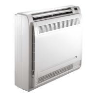
Fig. 2 – Installation of Fused Model Heater
3. For 5- through 20-kW circuit breaker models:
After installing heater assembly, attach circuit breaker assembly to
unit with screws provided (Fig. 3). On fan coil units size 42 and
larger, remove wire tie that shortens wire length between heater and
circuit breaker assembly to allow mounting of circuit breaker
assembly (Fig. 3).
A90153A
Fig. 3 – Installation of Circuit Breaker Model Heater
4. Circuit breaker models require installing a window bezel in unit
door to provide safe access to circuit breakers. The window bezel
mounts on the outside of the blower door (Fig. 4).
a. Cut insulation away from rectangular access hole in blower
access panel.
b. Remove adhesive backing from window bezel and from the
outside. Insert the window through the rectangular hole and seat
firmly on the door surface. Press firmly in place to seat the
adhesive (Fig. 4).
A03069
Fig. 4 – Installation of Window Bezel for Circuit Breaker Model
Heater
Procedure 3 — Electrical Connections
Refer to unit instructions for recommended wiring procedures. Install
wiring in accordance with all applicable local and national codes, see
Table 2 and Table 3. Connect heater wiring harness plug to receptacle on
PCB or wire harness. A positive connection must be made between plug
and receptacle. Plug will interlock with receptacle when properly seated.
Harness contains both 24V control and high-voltage wiring. Blower
power is provided through heater harness.
NOTE: Units with or without electric heaters require a minimum CFM.
Refer to unit wiring label to ensure the fan speed selected with electric
heaters is equal to or greater than the minimum fan speed indicated. The
minimum CFM for cooling is determined by the outdoor unit
requirements. Use the higher of the 2 for year-round operation.
Wire 24V Control Systems
1. Connections to Unit
Use No. 18 AWG color-coded, insulated (35°C minimum) wire to
make low-voltage connections between thermostat, fan coil unit,
and outdoor unit. If thermostat is located more than 100 ft (20 m)
from unit (as measured along the low-voltage wire), use No. 16
AWG color-coded, insulated (35°C minimum) wire. All wiring
must be separated from line voltage power leads. Refer to outdoor
unit wiring instructions for additional wiring procedure
recommendations.
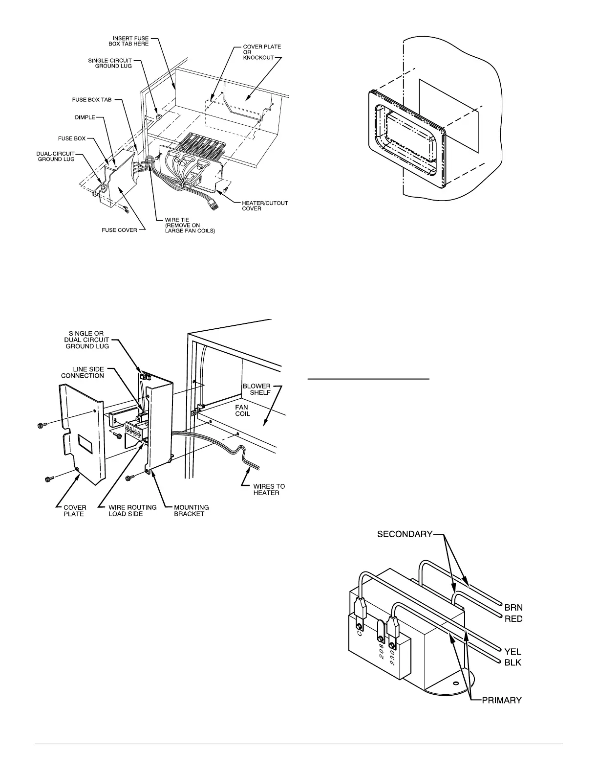
2. Transformer
Transformer is factory wired for 230V operation. For 208V
applications, disconnect black wire on transformer 230-v terminal
and reconnect it to 208V terminal (Fig. 5). The secondary circuit of
transformer is protected by a 5A fuse mounted on PCB.
A94067
Fig. 5 – Connection of Transformer
 Loading...