PG92MSA: Installation, Start-up, Operating and Service and Maintenance Instructions
Manufacturer reserves the right to change, at any time, specifications and designs without notice and without obligations.
5
2. Install this furnace only in a location and position as specified in the
“Location” section of these instructions.
3. Provide adequate combustion and ventilation air to the furnace
space as specified in “Air for Combustion and Ventilation” section.
4. Combustion products must be discharged outdoors. Connect this
furnace to an approved vent system only, as specified in the
“Venting” section of these instructions.
5. Never test for gas leaks with an open flame. Use a commercially
available soap solution made specifically for the detection of leaks
to check all connections, as specified in the “Gas Piping” section.
6. Always install furnace to operate within the furnace’s intended
temperature-rise range with a duct system which has an external
static pressure within the allowable range, as specified in the
“Start-Up, Adjustments, and Safety Check” section. See furnace
rating plate.
7. When a furnace is installed so that supply ducts carry air circulated
by the furnace to areas outside the space containing the furnace, the
return air shall also be handled by duct(s) sealed to the furnace
casing and terminating outside the space containing the furnace.
See “Air Ducts” section.
8. A gas-fired furnace for installation in a residential garage must be
installed as specified in the warning box in the “Location” section.
9. The furnace may be used for construction heat provided that the
furnace installation and operation complies with the first
CAUTION in the LOCATION section of these instructions.
10. These Multipoise Gas-Fired Furnaces are CSA design-certified for
use with natural and propane gases (see furnace rating plate) and for
installation in alcoves, attics, basements, closets, utility rooms,
crawlspaces, and garages. The furnace is factory-shipped for use
with natural gas. A CSA (A.G.A. and C.G.A.) listed accessory gas
conversion kit is required to convert furnace for use with propane
gas.
11. See Table 2 for required clearances to combustible construction.
Table 2 – Minimum Clearances to Combustible Materials
for All Units
12. Maintain a 1-in. (25 mm) clearance from combustible materials to
supply air ductwork for a distance of 36 in. (914 mm) horizontally
from the furnace. See NFPA 90B or local code for further
requirements.
13. These furnaces SHALL NOT be installed directly on carpeting,
combustible tile, or any other combustible material other than wood
flooring. In downflow installations, factory accessory floor base
MUST be used when installed on combustible materials and wood
flooring. Special base is not required when this furnace is installed
on manufacturer’s cased evaporator coils or when manufacturer’s
evaporator coil casing is used. See Table 2 for clearance to
combustible construction information.
INTRODUCTION
A12181
Fig. 2 – Multipoise Orientations
This 4-way multipoise Category IV condensing furnace is CSA
design-certified as a direct-vent (2-pipe) or non-direct vent (1-pipe)
furnace. See Fig. 2. The furnace is factory-shipped for use with natural
gas. The furnace can be converted in the field for use with propane gas
when a factory-supplied conversion kit is used. Refer to the furnace
rating plate for conversion kit information.
These furnaces are not approved for installation in recreational vehicles
or outdoors. Single-stage furnaces (40,000 through 120,000) are
approved for installation in manufactured housing/mobile homes with
manufacturer-approved accessory. The conversion kit is required for use
with both natural and propane gas. The furnace must also be installed on
a factory-supplied accessory combustible floor base or evaporator coil
casing.
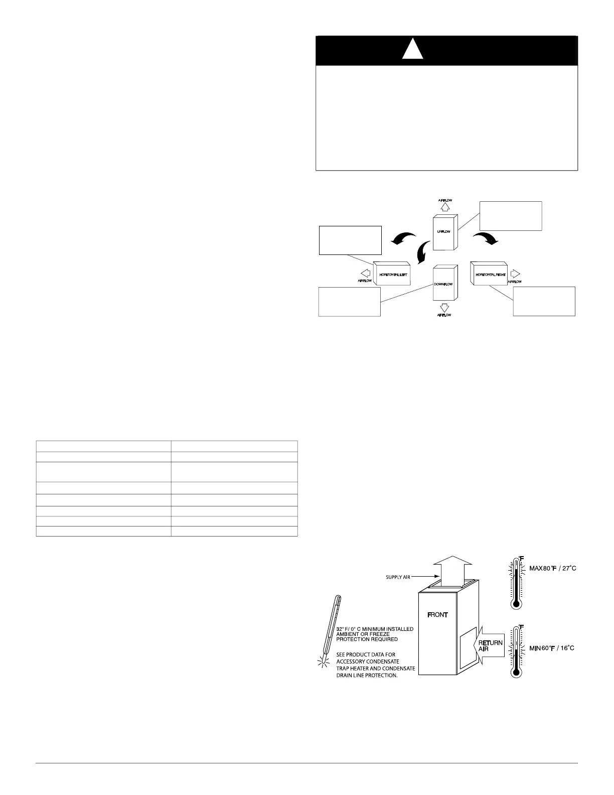
This furnace is designed for minimum continuous return-air temperature
of 60°F (15°C) db or intermittent operation down to 55°F (13°C) db such
as when used with a night setback thermostat. Return-air temperature
must not exceed 80°F (27°C) db. Failure to follow these return-air
temperature limits may affect reliability of heat exchangers, motors, and
controls. See Fig. 3.
A150573
Fig. 3 – Freeze Protection and Return Air Temperature
The furnace should be sized to provide 100 percent of the design heating
load requirement plus any margin that occurs because of furnace model
size capacity increments. None of the furnace model sizes can be used if
the heating load is 20,000 BTU or lower. Use Air Conditioning
Contractors of America (Manual J and S); American Society of Heating,
POSITION CLEARANCE
REAR 0
FRONT (Combustion air openings in
furnace and in structure)
1 in. (25 mm)
Required for service
*
24 in. (610 mm)
*. Consult local building codes
All Sides of Supply Plenum
*
1 in. (25 mm)
Sides 0
Vent 0
Top of Furnace 1 in. (25 mm)
NOTICE
!
Important Installation and Start-up Procedures
Failure to follow this procedure may result in a nuisance smoke or odor
complaint.
The manifold pressure, gas rate by meter clocking, temperature rise and
operation must be checked after installation. Minor smoke and odor
may be present temporarily after start-up from the manufacturing
process. Some occupants are more sensitive to this minor smoke and
odor. It is recommended that doors and windows be open during the
first heat cycle.
THE BLOWER IS LOCATED
TO THE RIGHT OF THE
BURNER SECTION, AND
CONDITIONED AIR IS
DISCHARGED TO THE LEFT.
THE BLOWER IS
LOCATED BELOW THE
BURNER SECTION, AND
CONDITIONED AIR IS
DISCHARGED UPWARD.
THE BLOWER IS
LOCATED ABOVE THE
BURNER SECTION, AND
CONDITIONED AIR IS
DISCHARGED DOWNWARD
THE BLOWER IS
LOCATED TO THE LEFT
OF THE BURNER SECTION,
AND CONDITIONED AIR IS
DISCHARGED TO THE RIGHT.