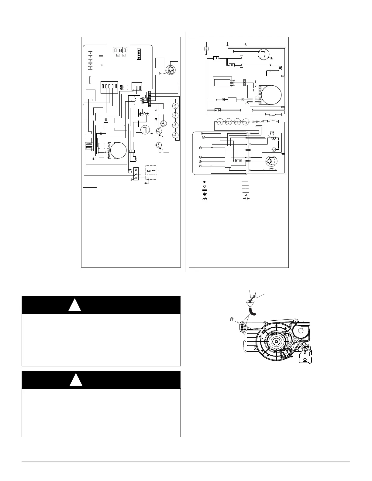
Fig. 62 – Wiring Diagram
1. Remove upper and middle collector box drain plugs opposite of the
condensate trap. See Fig. 63.
Fig. 63 – Priming Condensate Trap
2. Connect field-supplied 5/8-in. (16 mm) ID tube with attached
funnel to upper collector box drain connection.
3. Pour one quart (liter) of water into funnel/tube. Water should run
field drain.
4. Remove funnel; replace collector box drain plug.
5. Connect field-supplied 5/8-in. (16 mm) ID tube to middle collector
box drain port.
CONNECTION DIAGRAM
NOTES:
1
PRINTED CIRCUIT BOARD
WHT
FSE
NOTE #8
LGPS
(WHEN USED)
LPS
ORN
YEL
PL16
2
YEL
BRN
1
PL5
1
IDM
HSI
L1
FUSED OR CIRCUIT
BREAKER DISCONNECT
SWITCH (WHEN REQ’D)
GND
NEUTRAL
FU2
BLK
ILK
PL3
JB
1
2
BLK
WHT
TRAN
BLWM
NOTE #12
PL12
IND
NOTE #7
PL12
2
BLK
WHT
WHT
BLU
BLK
YEL
PL14
WHT
L
N
G
BLK
1
RED
GRN/YEL
BLK
NOTE #2
STATUS
CODE LED
24VAC HUM
FUSE3-AMP
W
Y
R
C
G
SEC-2
SEC-1
WHT
SEE R ATING PLA T EFO R
M ODEL P RO GR AM #
SEE INST ALLA TION INSTRUCTIONS
FOR AIR FLOW SETTINGS
L
E
G
E
N
D
BLWM
CPU
EAC-1
EAC-2
FRS
FSE
FU1
FU2
GV
GVR
HPS
HSI
HSIR
24VAC HUM
HUMR
IDM
IDR
ILK
IND
LED
LGPS
Blower Motor (ECM)
Microprocessor / Circuitry
DISP1
7-Segment display
Electronic Air Cleaner Connection
(115VAC 1.0 Amp Max.)
Electronic Air Cleaner Connection (Common)
Flame-Rollout Switch, Man. Reset, SPST (N.C.)
Flame Proving Sensor Electrode
Fuse, 3 Amp, Automotive Blade Type
Factory Installed
Fuse or Disconnect
Gas Valve
-redundant
Gas Valve Relay, SPST (N.O.)
Inducer Housing Pressure Switch, SPST (N.O.)
Hot Surface Igniter (115VAC)
Hot Surface Igniter Relay, SPST (N.O.)
24VAC Humidifier Connection (0.5 Amp Max.)
Humidifier Relay, SPST (N.O.)
Induced Draft Motor, ECM
Inducer Motor Relay, SPST (N.O.)
Blower Door Interlock Switch, SPST (N.O.)
Inductor (Note #7)
KY1
Next / Option Push Button
KY2
Menu / Select Push Button
Light Emitting Diode for Status Codes
Low Gas Pressure Switch, SPST (N.O.)
LPS
LS
PCB
PL1
PL2
PL3
PL5
PL12
PL13
PL14
PL16
TRAN
Collector Box Pressure Switch, SPST (N.O.)
Limit Switch, Auto-Reset, SPST (N.C.)
Printed Circuit Board
11-Circuit PCB Connector
2-Circuit HSI & IDM Connector
2-Circuit HSI Connector
4-Circuit Super Plug Connector
1-Circuit Inductor Splice Connector
5 or 6 Circuit ECM Blower CTRL Connector
3 or 4 Circuit ECM Blower Power Connector
3-Circuit PWM Connector
Transformer, 115VAC / 24VAC
JUNCTION TERMINAL
CONTROL TERMINAL
PCB CONTROL TERMINAL
FIELD EARTH GROUND
EQUIPMENT GROUND
FACTORY POWER WIRING (115VAC)
FACTORY CONTROL WIRING (24VAC)
FIELD CONTROL WIRING (24VAC)
CONDUCTOR ON CONTROL
FIELD WIRING SCREW TERMINAL
PLUG RECEPTACLE
PL13
FRS2
LS1
REDRED
FRS1
RED
NOTE #3
GV
GRN/YEL
BLU
GRN/YEL
2
1
PL2
GRN/YEL
BLWM
NOTE #12
PL13
PL14
PL12
PL12
IND
NOTE #7
PL1-11
PL1-7
PL1-9
1
PL16
1
2
C
L
G
N
NOTE #5
PCB
CPU
SCHEMATIC DIAGRAM
BL
EACR
EAC-1
EAC-2
FRS2
LS1
FRS1
(WHEN USED)
PL1-6
LS2
HUM
24VAC
PL1-8
NOTE #5
GVR
PCB
CPU
PL1-2
PL1-4
PL1-3
PL1-10
PL1-1
FSE
24VAC
N
PR
N
115VAC
SEC1
TRAN
N
FU1
SEC2
NOTE #6
N
ILK
N
TO 115VAC FIELD - DISCONNECT SWITCH
EQUIPMENT
GROUND
1
HSI
2
PL3
IDM
HSIR
1
2
PL2
IDR
LGPS
LPS
(WHEN USED)
NOTE #3
GV
NOTE #8
L1
NOTE #2
PL1-5
1. If any of the original equipment wire is replaced use wire rated f or 105ºC.
2. Use only copp er wire be tween the disconnect switch and the f urnace junction box (JB).
3. This wire must be connected to f urnace sheet metal f or con trol to prove flam e.
4. Symbols are elec trical representation onl y.
5. Solid lines inside PCB are printed c ircuit bo ard conduct ors and are not included in
legen d.
6. Replace only with a 3 amp fus e.
7. Inductor may be used with 3/4 hp and 1 hp ECM Blower motors. Review motor instructions
if replacing motor to see if Inductor is required.
8. Factory connected when L GPS is not use d.
9. Blower-off delay: gas heating selections are 90, 120, 150 or 180 seconds, cooli ng
or heat pump 90, 30 seconds o r 5 seconds .
10. Ignitio n-lockout will occ ur after four consecutive unsuccessful trials-for-ignitio n.
Control will aut o-reset aft er three ho urs.
11. Induc er (IDM) mot or contains int ernal aut o-reset th ermal ov erload switches (OL).
12. PL 13 and PL14 not available on all motors. Blower motor (BLWM) leads may be
hardwired at motor. Depending on motor type, 24V Common wire may be in either
CTRL (PL5) or Power (PL6) Connector
13. N connections are int erchangeable within the N connect or bloc k.
14. BLWM is locked - rotor overload protected by redundant elec tronic con trol c ircuit s.
C
RED
RED
W
R
C
Y
G
HPS
BRN
HPS
LS2
(WHEN USED)
PL1
DISP1
KY1
NEXT OPTION
MENU SELECT
KY2
L1
PR
BL
EAC-1
NOTE #13
EAC-2
NEUTRAL-L2
WHT
BLK
ORG
4
BRN
3
2
3
4
1
5
death.
or performance satisfaction.