PG92MSA: Installation, Start-up, Operating and Service and Maintenance Instructions
Manufacturer reserves the right to change, at any time, specifications and designs without notice and without obligations.
55
6. Pour one quart (liter) of water into funnel/tube. Water should run
through collector box, overfill condensate trap, and flow into open
field drain.
7. Remove funnel and tube from collector box and replace collector
box drain plug.
Purge Gas Lines
If not previously done, purge the lines after all connections have been
made and check for leaks.Table 25
ADJUSTMENTS
A93059
Fig. 64 – Orifice Hole
For proper operation and long term reliability, the Furnace input rate
must be within +/-2 percent of input rate on furnace rating plate, or as
adjusted for altitude.
The gas input rate on rating plate is for installations at altitudes up to
2000 ft. (609.6M).
In the USA., the input rating for altitudes above 2000 ft. (609.6M) must
be reduced by 2 percent for each 1000 ft. (304.8M) above sea level.
Refer to Table 25. The natural gas manifold pressures in Table 25 adjust
for BOTH altitude and natural gas heating value.
In Canada, the input rating must be reduced by 5 percent for altitudes of
2000 ft. (609.6M) to 4500 ft. (1371.6M) above sea level. The natural gas
manifold pressures in Table 25 adjust for BOTH altitude and natural gas
heating value.
Table 23 – Altitude Derate Multiplier for U.S.A.
*Derate multiplier factors are based on midpoint altitude for altitude range.
NOTE: For Canadian altitudes of 2000 to 4500 ft. (610 to 1372 M), use
USA altitudes of 2001 to 3000 ft. (611 to 914 M) in Table 23.
To adjust manifold pressure to obtain the proper input rate, first,
determine if the furnace has the correct orifice installed. At higher
altitudes or different gas heat contents, it may be necessary to change the
factory orifice to a different orifice. Tables have been provided in the
furnace installation instructions to match the required orifice to the
manifold pressure to the heat content and specific gravity of the gas. To
do this:
1. Obtain average yearly gas heat value (at installed altitude) from
local gas supplier.
2. Obtain average yearly gas specific gravity from local gas supplier.
3. Find installation altitude in Table 23.
4. Find closest natural gas heat value and specific gravity in Table 25.
Follow heat value and specific gravity lines to point of intersection
to find orifice size and manifold pressure settings for proper
operation.
5. Check and verify burner orifice size in furnace. NEVER ASSUME
ORIFICE SIZE. ALWAYS CHECK AND VERIFY.
6. Replace orifice with correct size, if required by Table 25. Use only
factory-supplied orifices. See EXAMPLE 1.
EXAMPLE 1: 0 - 2000 ft. (0 - 609.6M) altitude
WARNING
!
FIRE OR EXPLOSION HAZARD
Failure to follow this warning could result in personal injury, death,
and/or property damage.
Never purge a gas line into a combustion chamber. Never test for gas
leaks with an open flame. Use a commercially available soap solution
made specifically for the detection of leaks to check all connections. A
fire or explosion may result causing property damage, personal injury
or loss of life.
WARNING
!
FIRE HAZARD
Failure to follow this warning could result in personal injury, death
and/or property damage.
DO NOT bottom out gas valve regulator adjusting screw. This can
result in unregulated manifold pressure and result in excess overfire and
heat exchanger failures.
CAUTION
!
FURNACE DAMAGE HAZARD
Failure to follow this caution may result in reduced furnace life.
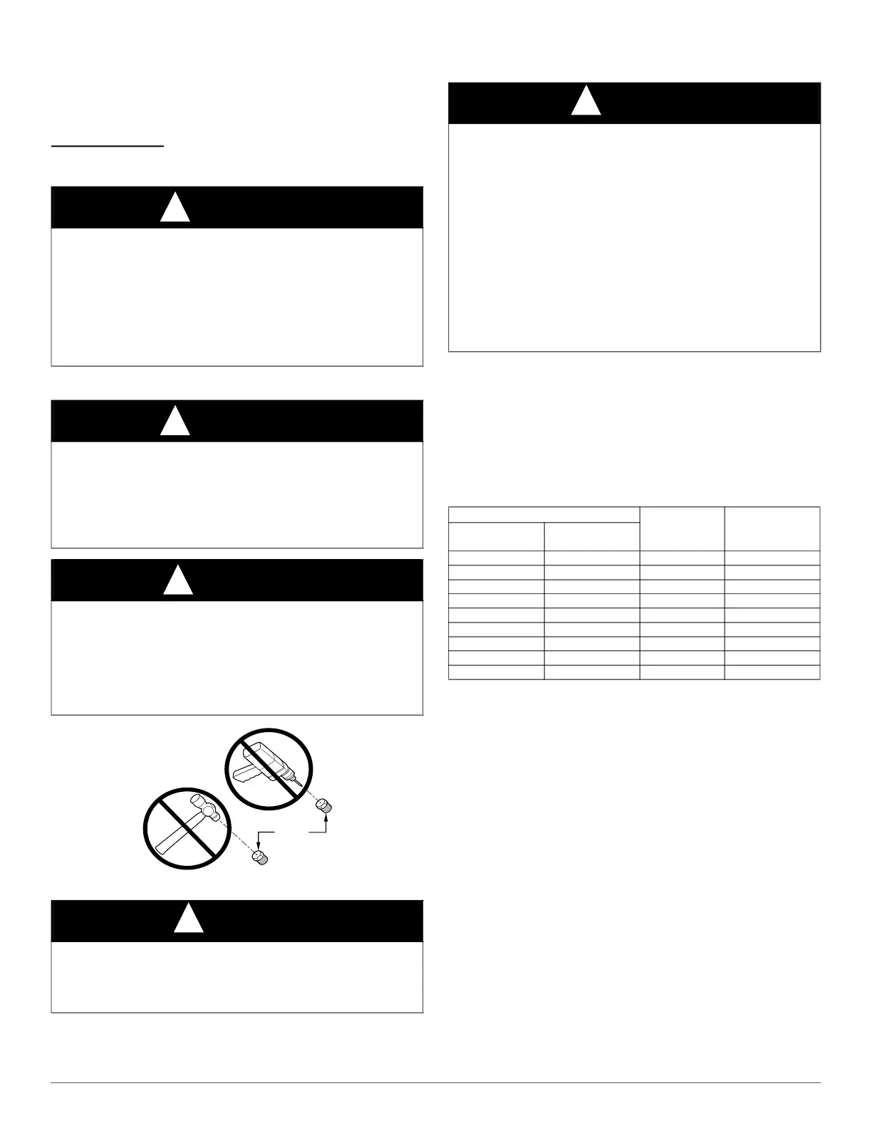
DO NOT redrill orifices. Improper drilling (burrs, out-of-round holes,
etc.) can cause excessive burner noise and misdirection of burner
flames. This can result in flame impingement of heat exchangers,
causing failures. See Fig. 64.
NOTICE
!
If orifice hole appears damaged or it is suspected to have been redrilled,
check orifice hole with a numbered drill bit of correct size. Never
redrill an orifice. A burr-free and squarely aligned orifice hole is
essential for proper flame characteristics.
NOTICE
!
The NATURAL GAS manifold pressure adjustments in Table 25
compensate for BOTH altitude AND gas heating value. DO NOT apply
an additional de-rate factor to the pressures show in Table 25. The
values in this table are NOT referenced to sea level; they are
AS-MEASURED AT ALTITUDE.
The heating content of natural gas at altitude may already provide for a
reduction in capacity of the furnace. Be sure to obtain the expected
in-season gas heating value of the gas from the gas supplier BEFORE
making any adjustments for capacity or altitude. Refer to Table 25. No
adjustments to the furnace may be necessary at altitude for certain gas
heating values.
Refer to the instructions provided in the factory-specified LP/Propane
conversion kit for instructions for setting gas manifold pressures for
LP/Propane applications.
ALTITUDE PERCENT
OF
DERATE
DERATE
MULTIPLIER
FACTOR*
FT. M
0–2000 0-610 0 1.00
2001–3000 610-914 4-6 0.95
3001–4000 914-1219 6-8 0.93
4001–5000 1219-1524 8-10 0.91
5001–6000 1524-1829 10-12 0.89
6001–7000 1829-2134 12-14 0.87
7001–8000 2134-2438 14-16 0.85
8001–9000 2438-2743 16-18 0.83
9001–10,000 2743-3048 18-20 0.81