51801210406 09/2019
Specifications are subject to change without notice.
INSTALL
TION INSTRUCTIONS
15 SEER 2--Stage Package Heat Pump System with R--410A
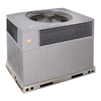
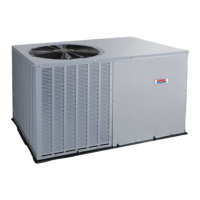
PHR524--60
1&3Phase
IMPORTANT: Effective January 1, 2015, all split system and
packaged air conditioners must be installed pursuant to applicable
regional efficiency standards issued by the Department of Energy.
NOTE: Read the entire instruction manual before starting the
installation.
NOTE: Installer: Make sure the Owner’s Manual and Service
Instructions are left with the unit after installation.
TABLE OF CONTENTS
PAGE
SAFETY CONSIDERATIONS 1.........................
INTRODUCTION 2...................................
RECEIVING AND INSTALLATION 2--10.................
Check Equipment 2..................................
Identify Unit 2....................................
Inspect Shipment 2.................................
Provide Unit Support 2...............................
Roof Curb 2......................................
Slab Mount 2.....................................
Provide Clearances 6.................................
Field Fabricate Ductwork 6............................
Rig and Place Unit 6.................................
Inspection 7......................................
Rigging/Lifting of Unit 7............................
Connect Condensate Drain 7...........................
Install Duct Connections 7.............................
Configuring Units for Downflow (Vertical) Discharge 8....
Install Electrical Connections 9.........................
High-- Voltage Connections 9.........................
Special Procedures for 208v Operation 9................
Control Voltage Connections 9........................
Standard Connection 9..............................
Transformer Protection 10...........................
PRE --START--UP 11...................................
START--UP 11--13.....................................
Check Cooling and Heating Control Operation 11..........
Check for Refrigerant Leaks 11.........................
Start--Up Adjustments 12..............................
Checking and Adjusting Refrigerant Charge 12...........
Indoor Airflow and Airflow Adjustments 12.............
Low Stage Cooling 13..............................
High Stage Cooling 13..............................
High Stage Enhanced Dehumidification Cooling (208/230 Vac
Models) 13.......................................
Continuous Fan 13.................................
Sequence of Operation 13...........................
Defrost Control 13...................................
Quiet Shift 13.....................................
Defrost 13.......................................
MAINTENANCE 28--31................................
Air Filter 28......................................
Indoor Blower and Motor 28.........................
Outdoor Coil, Indoor Coil, and Condensate Drain Pan 29...
Outdoor Fan 29...................................
Fig. 1 -- Unit PHR5
Electrical Controls and Wiring 29.....................
Refrigerant Circuit 30...............................
Evaporator Airflow 30..............................
Metering Device 30................................
System Information 31..............................
Loss of Charge Switch 31............................
Check Defrost Thermostat 31.........................
TROUBLESHOOTING 31..............................
START--UP CHECKLIST 31............................
SAFETY CONSIDERATIONS
Improper installation adjustment, alteration, service, maintenance,
or use can cause explosion, fire, electrical shock, or other
conditions which may cause death, personal injury, or property
damage. Consult a qualified installer, service agency, or your
distributor or branch for information or assistance. The qualified
installer or agency must use factory--authorized kits or accessories
when modifying this product Refer to the individual instructions
packaged with the kits or accessories when installing.
Follow all safety codes. Wear safety glasses, protective clothing,
and work gloves. Use quenching cloth for brazing operations.
Have a fire extinguisher available. Read these instructions
thoroughly and follow all warnings or cautions included in
literature and attached to the unit. Consult local building codes, the
current editions of the National Electrical Code (NEC) NFPA 70.
In Canada refer to the current editions of the Canadian electrical
Code CSA C22.1.
Recognize safety information. This is the safety-- alert symbol
.
When you see this symbol on the unit and in instructions or
manuals, be alert to the potential for personal injury. Understand
these sign al words; DANGER, WARNING, and CAUTION. These
words are used with the safety--alert symbol. DANGER identifies
the most serious hazards which will result in severe personal injury
or death. WARNING signifies hazards which could result in
personal injury or death. CAUTION is used to identify unsafe
practices which may result in minor personal injury or product and
property damage. NOTE is used to highlight suggestions which
will result in enhanced installation, reliability, or operation.