RHV-090-120-01SI 4-22
Installation Instructions
CONTENTS
Page
SAFETY CONSIDERATIONS . . . . . . . . . . . . . . . 1
MODEL NUMBER NOMENCLATURE AND
DIMENSIONS . . . . . . . . . . . . . . . . . . . . . . . . . . 2
Rated Indoor Airflow . . . . . . . . . . . . . . . . . . . . . 2
INSTALLATION . . . . . . . . . . . . . . . . . . . . . . . . . 10
Jobsite Survey . . . . . . . . . . . . . . . . . . . . . . . . . 10
Step 1 — Plan for Unit Location . . . . . . . . . . . 10
• ROOF MOUNT
Step 2 — Plan for Sequence of Unit
Installation . . . . . . . . . . . . . . . . . . . . . . . . . . . 10
• CURB-MOUNTED INSTALLATION
• PAD-MOUNTED INSTALLATION
• FRAME-MOUNTED INSTALLATION
Step 3 — Inspect Unit . . . . . . . . . . . . . . . . . . . . 10
Step 4 — Provide Unit Support . . . . . . . . . . . . 10
• ROOF CURB MOUNT
• SLAB MOUNT (HORIZONTAL UNITS ONLY)
• ALTERNATE UNIT SUPPORT (IN LIEU OF CURB OR
SLAB MOUNT)
Step 5 — Field Fabricate Ductwork . . . . . . . . . 12
• FOR UNITS WITH ACCESSORY ELECTRIC
HEATERS
Step 6 — Rig and Place Unit . . . . . . . . . . . . . . 12
• POSITIONING ON CURB
Step 7 — Convert to Horizontal and Connect
Ductwork (when required) . . . . . . . . . . . . . . 13
Step 8 — Install Outside Air Hood . . . . . . . . . 14
• ECONOMIZER HOOD PACKAGE REMOVAL
(FACTORY OPTION)
• ECONOMIZER HOOD SETUP
Step 9 — Install External Condensate Trap
and Line . . . . . . . . . . . . . . . . . . . . . . . . . . . . . 15
Step 10 — Make Electrical Connections . . . . . 15
• FIELD POWER SUPPLY
• FIELD POWER WIRING CONNECTIONS
• UNITS WITH FACTORY-INSTALLED NON-FUSED
DISCONNECT
• UNITS WITHOUT FACTORY-INSTALLED
NON-FUSED DISCONNECT
• ALL UNITS
• CONVENIENCE OUTLETS
• FACTORY OPTION THRU-BASE CONNECTIONS
• UNITS WITHOUT THRU-BASE CONNECTIONS
• FIELD CONTROL WIRING
• THERMOSTAT
• UNIT WITHOUT THRU-BASE CONNECTION KIT
• HEAT ANTICIPATOR SETTINGS
• COMMERCIAL DEFROST CONTROL
• ELECTRIC HEATERS
• SINGLE POINT BOXES AND SUPPLEMENTARY
FUSES
• SINGLE POINT BOXES WITHOUT FUSES
• LOW-VOLTAGE CONTROL CONNECTIONS
• CONTROL AND POWER WIRING DIAGRAMS
EconoMi$er X (Factory-Installed Option) . . . . 28
• PRODUCT DESCRIPTION
• SYSTEM COMPONENTS
• SPECIFICATIONS
•INPUTS
•OUTPUTS
• ENVIRONMENTAL
• ECONOMIZER MODULE WIRING DETAILS
• S-BUS SENSOR WIRING
• CO2 SENSOR WIRING
• INTERFACE OVERVIEW
• USER INTERFACE
• KEYPAD
• MENU STRUCTURE
• SETUP AND CONFIGURATION
• TIME-OUT AND SCREENSAVER
• STANDARD OR SINGLE SPEED FAN OPERATION
• 2 SPEED FAN OPERATION
• 2SP H/C (2 SPEED HEAT/COOL) SPEED FAN
OPERATION
• 3 SPEED FAN OPERATION
• ENTHALPY SETTINGS
•CHECKOUT
• TROUBLESHOOTING
Controller Options . . . . . . . . . . . . . . . . . . . . . . 39
• LOW AMBIENT
Smoke Detectors . . . . . . . . . . . . . . . . . . . . . . . 39
• COMPLETING RETURN AIR SMOKE SENSOR
INSTALLATION
• ADDITIONAL APPLICATION DATA
Step 11 — Adjust Factory-Installed Options . 40
•SMOKE DETECTORS
Step 12 — Install Accessories . . . . . . . . . . . . 40
Step 13 — Fan Speed Set Up . . . . . . . . . . . . . 41
• UNITS WITH ELECTRO-MECHANICAL CONTROLS
Typical Unit Piping . . . . . . . . . . . . . . . . . . . . . . 43
Pre-Start and Start-Up . . . . . . . . . . . . . . . . . . . 47
START-UP CHECKLIST. . . . . . . . . . . . . . . . . CL-1
SAFETY CONSIDERATIONS
Improper installation, adjustment, alteration, service,
maintenance, or use can cause explosion, fire, electrical
shock or other conditions which may cause personal injury
or property damage. Consult a qualified installer, service
agency, or your distributor or branch for information or
assistance. The qualified installer or agency must use
factory-authorized kits or accessories when modifying this
product. Refer to the individual instructions packaged with
the kits or accessories when installing.
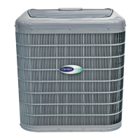
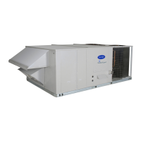
RHV090-120
Single Package Rooftop Heat Pump
with R-410A Refrigerant
and X-Vane Fan Technology



 Loading...