P/N: 387347 REV: 5.0 01JUN07 Installation Sheet
2 / 3 Signature Series Riser Monitor Module (RM1)
Installation instructions
Note: The RM1 is shipped from the factory as an assembled
unit; it contains no user-serviceable parts and should not be
disassembled.
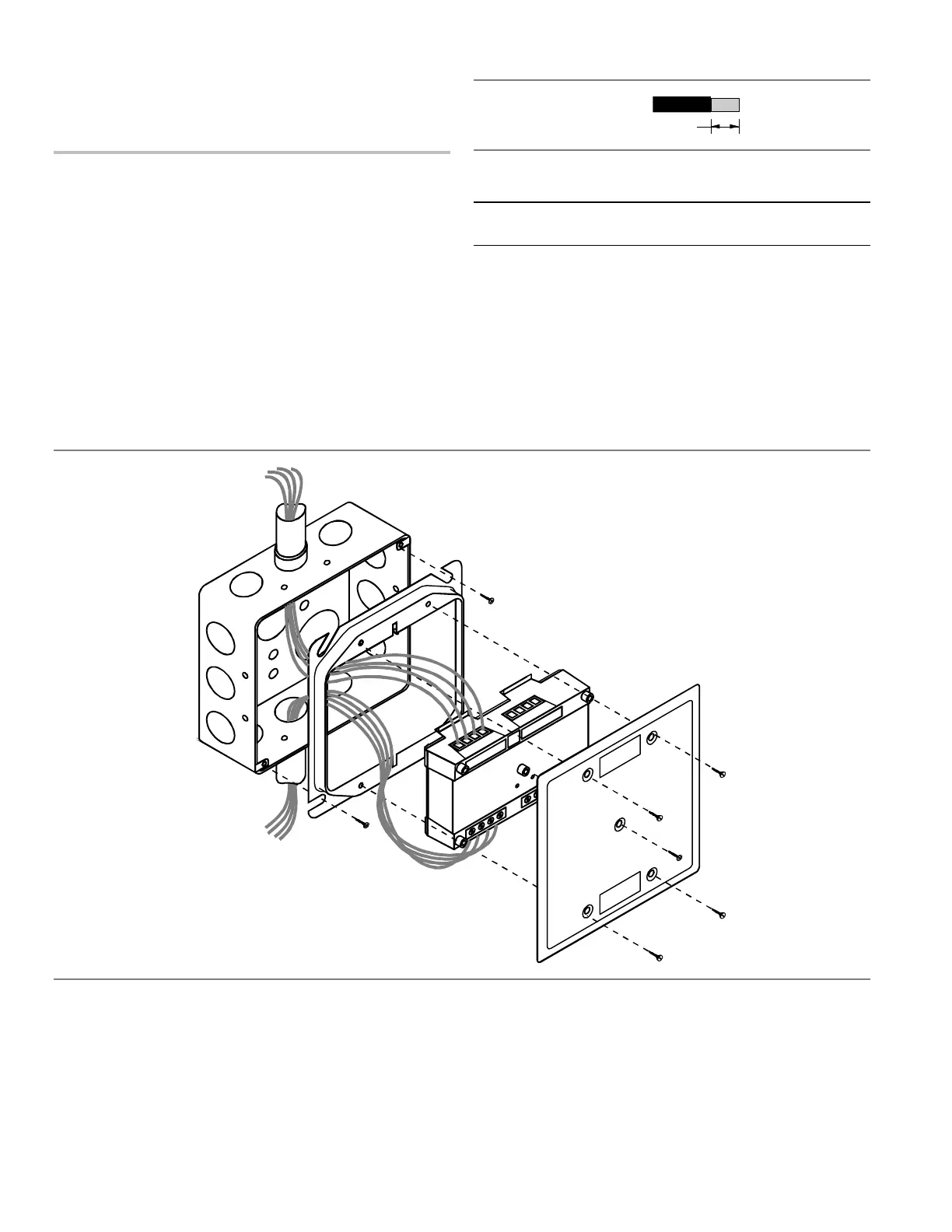
To install the module:
1. Verify that all field wiring is free of opens, shorts, and
ground faults.
2. Make all wiring connections as shown in the wiring
diagram.
3. Write the address assigned to the module on the label
provided and apply the label to the module. Peel off the
removable serial number label from the module and apply
it to the appropriate location in the serial number logbook.
4. Using the 4-24 x 5/16 in (8 mm) self-tapping screw
provided, mount the wall plate to the module.
5. Using the four 6-32 x 1/2 in (13 mm) machine screws
provided, mount the module to the electrical box.
Note: Wire in accordance with NFPA 70 National Electrical
Code.
Wire stripping guide
1/4 in (~6 mm)
Strip 1/4 in (about 6 mm) from the ends of all wires that
connect to the terminal block of the module.
Caution: Exposing more wire may cause a ground fault.
Exposing less wire may result in a faulty connection.
 Loading...