Installation Sheet 01JUN07 P/N: 387347 REV: 5.0
Signature Series Riser Monitor Module (RM1) 3 / 3
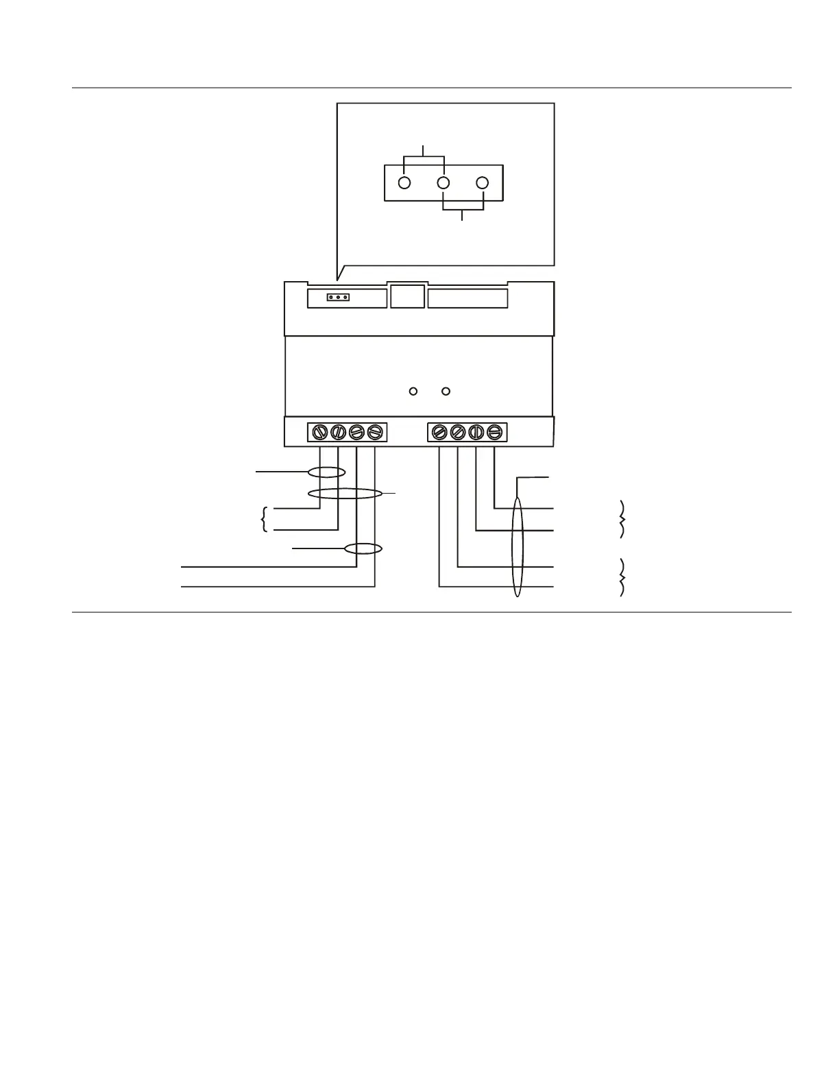
Wiring diagram
12345678
Data out (-)
Data out (+)
Data in (-)
Data in (+)
From Signature loop controller
or previous device
To Signature device
12 Vdc, 24 Vdc, 25 Vac, or 70 Vac
riser from power supply or audio
amplifier (not polarity sensitive)
Telephone riser (+)
Telephone riser (-)
12 Vdc, 24 Vdc, or 25 Vac
70 Vac
JP1
Jumper settings
Note:
Leave the jumper out for telephone
riser operation.
[2]
[3] [8]
[4]
Green LED
[1]
[2]
[5]
[6] [7]
Notes
[1] Supervised and power-limited
[2] 12 AWG (2.5 sq mm) max; 18 AWG (0.75 sq mm) min
[3] See the Signature loop controller installation sheet for
wiring specifications
[4] Supervised and power-limited unless connected to a
nonpower-limited source. If the source is nonpower-
limited, eliminate the power-limited mark and:
• Maintain a 1/4 inch (6.4 mm) space from power-
limited wiring
or
• Use FPL, FPLR, FPLP, or an equivalent cable in
accordance with NFPA 70 National Electric Code
Wire size must be capable of handling fault current from
nonpower-limited source.
[5] Active when communicating with the Signature loop
controller
[6] You cannot use the telephone riser while you use the 12
and 24 Vdc, 25 Vac, or 70 Vac riser
[7] Riser circuits are Style 4 (Class B)
[8] Data circuits are Style 4 (Class B) or Style 6 (Class A)
 Loading...