6-12T -309
the refrigeration unit into the container. The fan motor
bearings are factory lubricated and do not require
additional grease.
6.17.1 Replacing The Evaporator Fan Assembly
WARNING
Always turn OFF the unit circuit breakers
(CB-1 & CB-2) and disconnect main power
supply before working on moving parts.
a. Remove upper access panel (see Figure 2-2) by
removing mounting bolts and T.I.R. locking device.
Reach insideof unit andremovethe Ty-Rapsecuring
thewireharness loop. Then unplug the connectorby
twisting to unlock and pulling t o separate. NOTE: It
maybeeasiertounplugtheconnectorwiththemotor
assembly partially pulled out (after step b).
b. Remove the four mounting bolts that secure the mo-
tor--fan assembly to the unit.
c. Slide the fan assembly out from the unit and place it
on a sturdy work surface.
d. Remove the motor and fan from the assembly.
e. Replace the motor.
f. Lubricate the fan m otor shaft with a graphite--oil
solution (Never--Seez) and apply thread sealer (Loc-
tite H, brown in color) to the two fan set screws.
Installfanonthemotorshaft,sothatthecouplingsur-
face will be even with the end of the motor shaft.
g. Install the fan assembly in reverse order of removal.
Apply power momentarily to check for proper fan
rotation(refertoparagraph2.3).Ifthefanspinsback-
wards, than motor wiring or motor is defective.
Replace access panel making sure that panel does not
leak. Lock--wire the T.I.R. locking device(s).
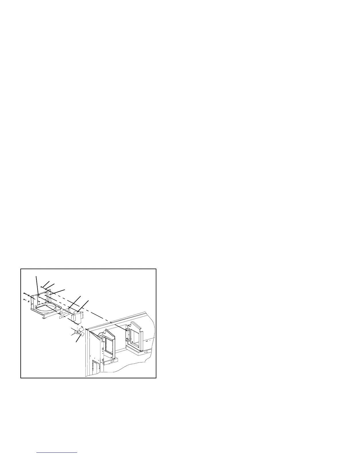
1
2
3
4
5
6
7
8
9
1. Bracket
2. Flat washer, 3/8
3. Bolt, 3/8-16 x 1.00
4. Locknut, 5/16-18
5. Flat washer, 5/16
6. Cap Screw, Hxhd
5/16-18 x 1.25
7. Fan
8. Shim
9. Evaporator Motor
Figure 6-16. Evaporator Fan Assembly
6.18 EVAPORATOR FAN MOTOR CAPACITORS
The evaporator fan motors are of the permanent-split
capacitor type. The motor i s equipped with one
capacitor used in the high speed circuit and another
capacitor used for the low speed circuit.
6.18.1 When To Check For A Defective Capacitor
a. Fanmotorwillnotchangespeed.Forexample:inthe
conventionalperishablem ode,themotorsshouldrun
in high speed. In the economy perishable modethey
shouldswitchspeedsandinthefrozenmode,themo-
tors should run in low speed.
NOTE
The evaporator fan motors will always start in
high speed.
b. Motor running in wrong direction (after checking
for correct wiring application).
c. Motor will not start, and IP-EM’s are not open.
6.18.2 Removing The Capacitor
WARNING
Make sure power to the unit is OFF and
power p lug disconnected before removing
capacitor(s).
The capacitors are located on the motor and above the
evaporator fan deck they may be removed by two
methods:
1 If container is empty, open upper rear panel of the
unit.Thecapacitormaybeservicedafterdisconnect-
ing power plug.
2 If containeris full, turn theunit powerOFF anddis-
connect power plug. Remove the evaporator fan
motor access panel. (See see Figure 2-1). For
removal of theevaporatorfan assembly, refertosec-
tion 6.17.
WARNING
WithpowerOFFdischargethecapacitorbe-
fore disconnecting the circuit wiring.
6.18.3 Checking The Capacitor
If the capacitor i s suspected of malfunction, you may
choosetosimplyreplaceit.Directreplacementrequires
a capacitor of the same value. Two methods for
checking capacitor function are:
1. Volt-ohmmeter set on RX 10,000 ohms.
Connect ohmmeter leads across the capacitorterminals
and observe the m eter needle. If the capacitor is good,
the needle will make a rapid swing toward zero
resistance and then gradually swing backtoward a very
high resistance reading.
If the capacitor has failed open, the ohmmeter needle
will not move when the meter probes touch the
terminals. If the capacitor is shorted, the needle will
swing to zero resistance position and stay there.
2. Capacitor analyzer:
The function of the analyzer is to read the microfarad
valueof a capacitor and to detect insulation breakdown

 Loading...