12
BLOWER ON DELAY -- Time after hot water is requested that the
blower will turn on.
S Available settings -- 0 to 240 seconds in 30 second incre-
ments
S Default is 30
BLOWER OFF DELAY-- Time after hot water request terminates
before the blower will turn off.
S Available settings -- 0 to 240 seconds in 30 second incre-
ments
S Default is 0.
Setup -- Accessories
Filter T ype:
S MEDIA (i.e. TrueSenset)
S EAC
S MEDIA+EAC (i.e. TrueSen set)
CLEAN INTERVAL: 30 to 180 days (of actual blower operation).
(Default = 90)
Interval at which the Clean Filter notification will turn on. Applies
to EAC filter selection only.
Humidifier
Installed:
S NO
S YES
If YES, indicates to the system whether a humidifier is installed
and enables humidification functions.
CHANGE PAD INTERVAL: 1 to 24 months (default=12 mo nths)
Interval at which the Change Humidify Pad notification will be
displayed.
HUMIDIFY WITH FAN:
S NO (default)
S YES
If YES, the humidifier will turn on if there is a humidify demand
present. The fan will turn on to Low speed if the fan setting is
Auto.
V
entilator:
NOTE: Only appears if ventilator is installed.
CLEAN INTERVAL:
S 60 to 180 days of actual operation (default=90)
Interval at which the Clean Ventilator Pre--filter notification will
turn on.
UV Lights
Installed
S NO
S YES
If YES, indicates to the system whether UV lights are installed.
CHANGE INTERVAL:
S 6 to 48 months operation time (default=12 months)
Interval at which the Change UV Lights notification will be
displayed.
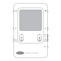
Setup -- System Maintenance
Remind Owner of Routine Maintenance Every:
This setup is used to adjust the timer interval in which the normal
System Maintenance notification is turned on for the homeowner.
(See Fig. 30.)
Range =
S OFF
S 6 to 24 months, (default=12 months)
SYSTEM MAINTENANCE
< BACK
REMIND OWNER OF
MAINTENANCE EVERY:
12 MONTHS
% USED: 50%
RESET >
A07033
Fig. 30 -- System Maintenance
Pressing the right side button will reset the timer. Pop--up
confirmation will be shown.
Setup -- Utility Saver
Cooling/Heat Pump Heating:
S Turn of f, Low Stage
This setup is available only if the equipment has a utility saver
input (refer to equipment Installation Instructions.) This setup
controls the response of the equipment when the utility saver input
is active.
The choices include:
S Turn Off , (equipment turns off)
S Low Stage (available if the AC/heat pump is a 2 -- stage
model, runs low speed only)
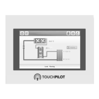
CHECKOUT MENUS
The Checkout menu will show the equipment installed in the
system. A sample checkout menu is shown in Fig. 31.
CHECKOUT
FURNACE
HEAT PUMP HEATING
HEAT PUMP COOLING
HUMIDIFIER
VENTILATOR
BACK SELECT
A03204
Fig. 31 -- Checkout Menu
Checkout -- Furnace or Gas PAC
Make sure the furnace is properly installed before continuing.
S LOW HEAT RUNTIME: 5 min.
S HIGH HEAT RUNTIME: 5 min.
This menu item allows the furnace to be exercised. First, a low heat
runtime and high heat runtime are selected. Range = 5 -- 120 min.
If only the low heat is to be exercised:
The furnace will execute its ignition start--up sequence. This
sequence will be displayed on the Infinity Control screen. After the
gas valve and blower motor turn on, the screen will automatically
change to “FURNACE CHECK” and show the current operating
status of the furnace.
Checkout -- Electric Heat
S ELECTRIC HEAT RUNTIME: 5 min., Default time = 5
min., Range = 0 -- 120 min.
If you have a fan coil with electric heaters, this menu item will
allow the heaters to be exercised.
With self--identifying electric heaters, three stages of electric heat
are available to be exercised in any combination. Non -- identifying
heaters will only provide one stage of heat.
Enter the run time (in minutes) of each stage of heat to be exercised
then press START (right-- side button). The display will change to
show the fan coil’s operating status.
CCUID01-- B

 Loading...