7–33 T-340
13. Position sensor in unit (see Figure 7.18) and re-check sensor resistance.
14. Reinstall sensor (see Section 7.24.3).
NOTE
The P5 Pre-Trip test must be run to deactivate probe alarms (see Section 5.9).
7.24.3 Sensors STS and SRS Reinstallation
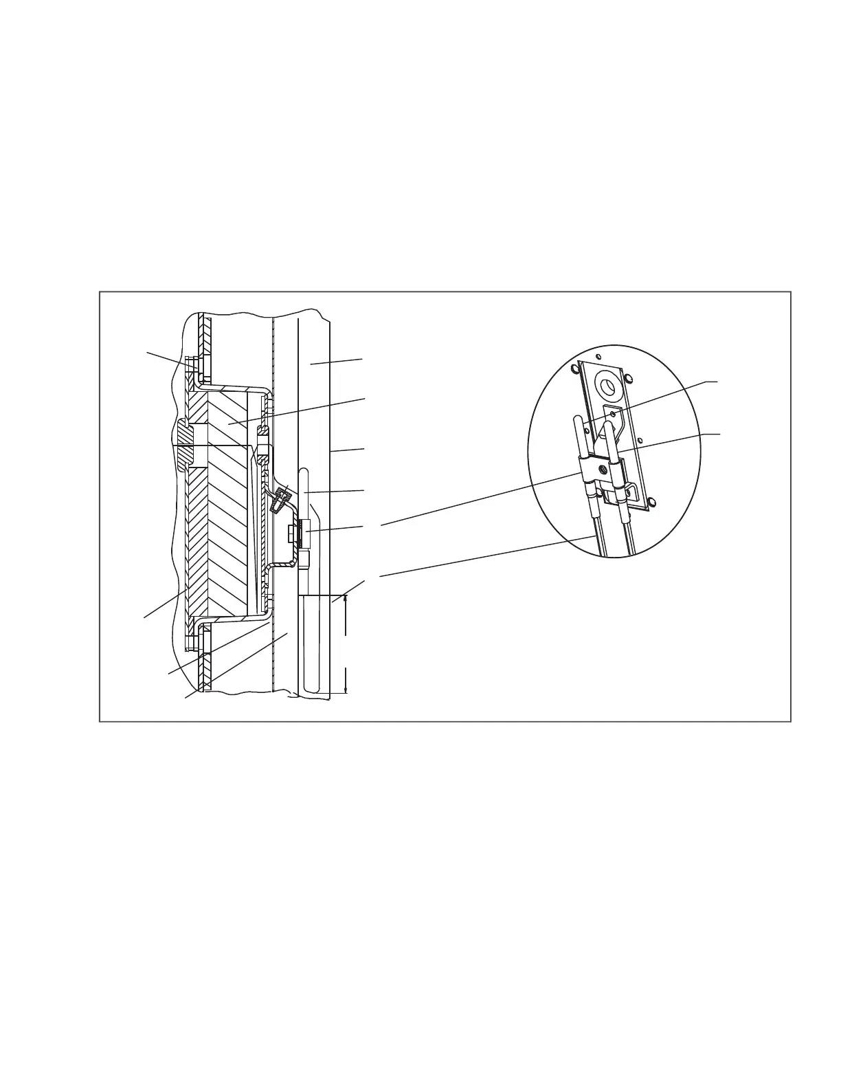
To properly position a supply sensor, the sensor must be fully inserted into the probe holder mounting clamp. See
Figure 7.19. Do not allow heat shrink covering to contact the probe holder. For proper placement of the sensor, be
sure to position the enlarged positioning section of the sensor against the side of the mounting clamp. This position-
ing will give the sensor the optimum amount of exposure to the supply air stream, and will provide accurate tempera-
ture readings to the controller.
Figure 7.19 Supply Sensor Positioning
1) Supply Air Stream
2) Insulation
3) Back Panel
4) Supply Sensor
5) Mounting Clamp
6) Sensor Wires
7) Drip Loop
8) Gasket Mounting Plate
9) Gasketed Support Plate
10) Gasketed Cover
11) TIR Bolts
12) STS Probe
13) SRS Probe
- - - - -
1
2
3
4
5
7
6
8
9
10
11
12
13

 Loading...