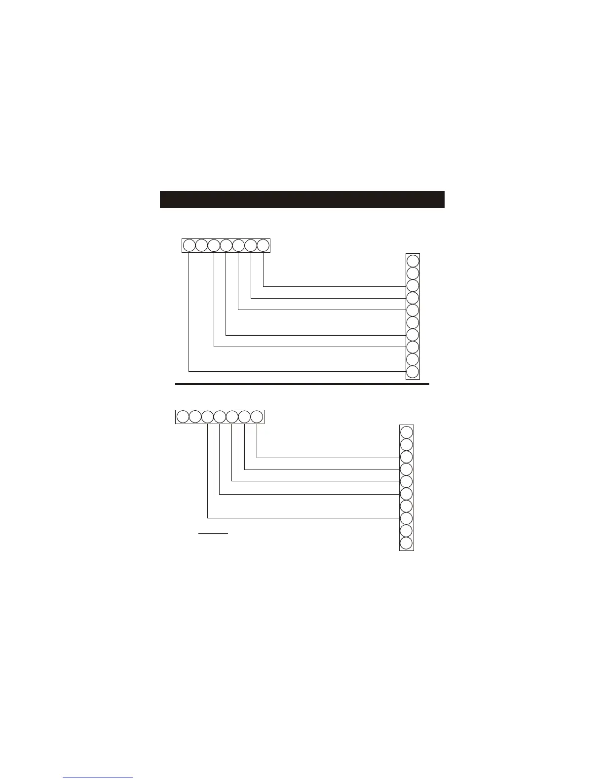
Sample Wiring Diagrams
Page 6
R
C
G
Y1
Y2
W1
W2
O
E
L
R
C
G
Y1
Y2
W1
W2
O
24 vac common
24 vac return
fan relay
compressor relay
1st stage heat circuit
2nd stage heat circuit
Residential & commercial 1 Stage Cooling,
with 2 Stage Gas or Electric Heat*
6 Wire, 1 Stage Cooling, 2 Stage Heat
Thermostat
R
C
G
Y1
Y2
W1
W2
O
E
L
R
C
G
Y1
Y2
W1
W2
O
24 vac common
24 vac return
fan relay
compressor relay
reversing valve
No auxiliary heat, residential Heat Pumps ,
split systems & package units
5 Wire, 1 Stage Cooling, 1 Stage Heat - Heat Pump*
Thermostat
* If using residential heat pump, this option
must be selected on during advanced setup.
 Loading...