Manufacturer reserves the right to discontinue, or change at any time, specifications or designs without notice and without incurring obligations.
Catalog No. 04-53480183-01 Printed in U.S.A. Form 48LC-14-26-06SI Pg 1 8-19 Replaces: 48LC-14-26-05SI
Installation Instructions
NOTE: Read the entire instruction manual before starting the
installation.
CONTENTS
SAFETY CONSIDERATIONS . . . . . . . . . . . . . . . . . . . . 1
GENERAL . . . . . . . . . . . . . . . . . . . . . . . . . . . . . . . . . . . 2
Rated Indoor Airflow (cfm) . . . . . . . . . . . . . . . . . . . . . 2
INSTALLATION. . . . . . . . . . . . . . . . . . . . . . . . . . . . . . 19
Step 1 — Plan for Unit Location . . . . . . . . . . . . . . . . 19
• ROOF MOUNT
Step 2 — Plan for Sequence of Unit Installation . . . 19
• CURB-MOUNTED INSTALLATION
• PAD-MOUNTED INSTALLATION
• FRAME-MOUNTED INSTALLATION
Step 3 — Inspect Unit . . . . . . . . . . . . . . . . . . . . . . . . 19
Step 4 — Provide Unit Support. . . . . . . . . . . . . . . . . 19
• ROOF CURB MOUNT
• SLAB MOUNT (HORIZONTAL UNITS ONLY)
• ALTERNATE UNIT SUPPORT (IN LIEU OF CURB OR
SLAB MOUNT)
Step 5 — Field Fabricate Ductwork . . . . . . . . . . . . . 23
Step 6 — Rig and Place Unit . . . . . . . . . . . . . . . . . . . 23
• POSITIONING ON CURB
Step 7 — Horizontal Duct Connection . . . . . . . . . . . 24
Step 8 — Install Outside Air Hood — Factory
Option . . . . . . . . . . . . . . . . . . . . . . . . . . . . . . . . . . . 24
Step 9 — Install Flue Hood and Combustion Air
Hood . . . . . . . . . . . . . . . . . . . . . . . . . . . . . . . . . . . . 26
Step 10 — Install Gas Piping. . . . . . . . . . . . . . . . . . . 26
• GAS SUPPLY LINE
• FACTORY-OPTION THRU-BASE CONNECTIONS
Step 11 — Install External Condensate Trap and
Line . . . . . . . . . . . . . . . . . . . . . . . . . . . . . . . . . . . . . 28
Step 12 — Make Electrical Connections . . . . . . . . . 29
• FIELD POWER SUPPLY
• UNITS WITHOUT FACTORY-INSTALLED NON-
FUSED DISCONNECT OR HACR
• UNITS WITH FACTORY-INSTALLED NON-FUSED
DISCONNECT OR HACR
• ALL UNITS
• CONVENIENCE OUTLETS
• HACR
• FACTORY-OPTION THRU-BASE CONNECTIONS
• UNITS WITHOUT THRU-BASE CONNECTIONS
• FIELD CONTROL WIRING
• THERMOSTAT
• UNIT WITHOUT THRU-BASE CONNECTION KIT
• HEAT ANTICIPATOR SETTINGS
• TRANSFORMER CONNECTION FOR 208-V POWER
SUPPLY
RTU Open Controller (Factory-Installed Option). . . 39
SystemVu™ Controller (Factory-Installed Option) . 39
Humidi-MiZer® System Control Connections . . . . . 39
• HUMIDI-MIZER SYSTEM – SPACE RH CONTROLLER
Integrated Staging Control (ISC) Board . . . . . . . . . . 40
• ISC BOARD - SEQUENCE OF OPERATION
EconoMi$er® X (Factory Option) . . . . . . . . . . . . . . 43
• SYSTEM COMPONENTS
• SPECIFICATIONS
•INPUTS
•OUTPUTS
• ENVIRONMENTAL
• ECONOMIZER MODULE WIRING DETAILS
• INTERFACE OVERVIEW
• SETUP AND CONFIGURATION
• ENTHALPY SETTINGS
• TWO-SPEED FAN OPERATION
• CHECKOUT
• TROUBLESHOOTING
Staged Air Volume (SAV™) with Variable Frequency
Drive. . . . . . . . . . . . . . . . . . . . . . . . . . . . . . . . . . . . 57
• MULTI-SPEED VFD DISPLAY KIT (FIELD-
INSTALLED OPTION)
• CONNECTING THE KEYPAD TO THE VFD
• PROGRAM THE VFD FOR INDOOR FAN CONTROL
Smoke Detectors. . . . . . . . . . . . . . . . . . . . . . . . . . . . 71
• RETURN AIR SENSOR TUBE INSTALLATION
• SMOKE DETECTOR TEST MAGNET
• ADDITIONAL APPLICATION DATA
Step 13 — Install Accessories . . . . . . . . . . . . . . . . . 71
Step 14 — Check Belt Tension . . . . . . . . . . . . . . . . 72
• BELT FORCE — DEFLECTION METHOD
• BELT TENSION METHOD
START-UP CHECKLIST . . . . . . . . . . . . . . . . . . . . CL-1
SAFETY CONSIDERATIONS
Installation and servicing of air-conditioning equipment can be
hazardous due to system pressure and electrical components. Only
trained and qualified service personnel should install, repair, or
service air-conditioning equipment.
Untrained personnel can perform basic maintenance functions of
cleaning coils and filters and replacing filters. All other operations
should be performed by trained service personnel. When working
on air-conditioning equipment, observe precautions in the litera-
ture, tags and labels attached to the unit, and other safety precau-
tions that may apply.
Follow all safety codes, including ANSI (American National Stan-
dards Institute) Z223.1. Wear safety glasses and work gloves. Use
quenching cloth for unbrazing operations. Have fire extinguisher
available for all brazing operations.
It is important to recognize safety information. This is the safety-
alert symbol . When you see this symbol on the unit and in in-
structions or manuals, be alert to the potential for personal injury.
Understand the signal words DANGER, WARNING, CAUTION,
and NOTE. These words are used with the safety-alert symbol.
DANGER identifies the most serious hazards which will result in
severe personal injury or death. WARNING signifies hazards
which could result in personal injury or death. CAUTION is used
to identify unsafe practices, which may result in minor personal
injury or product and property damage. NOTE is used to highlight
suggestions which will result in enhanced installation, reliability,
or operation.
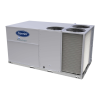
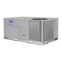
WeatherExpert
®
48LC 14-26
Single Package Rooftop
Gas Heat/Electric Cooling Unit
with Puron
®
(R-410A) Refrigerant


 Loading...