58
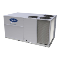
Fig. 65 — VFD Location
MULTI-SPEED VFD DISPLAY KIT (FIELD-INSTALLED
OPTION)
NOTE: The Remote VFD Keypad is part of the Multi-Speed VFD
display kit (PN: CRDISKIT002A00) which is a field-installed op-
tion. It is not included with the 48LC**14-26 base units.
Fig. 66 — VFD Keypad
The VFD keypad as shown in Fig. 66 consists of the following
sections.
Alpha Numeric Display
The LCD display is back lit with 2 alpha-numeric lines. All data is
displayed on the LCD. See Fig. 67.
Fig. 67 — Alphanumeric Display
Menu Key
Use the Menu key to select between Status, Quick Menu, or Main
Menu. The triangle icon at the bottom of the LCD display indi-
cates the currently selected mode. (See number 5 in Fig. 67.)
Navigation Keys and Status LEDs
The Navigation keys and Status LEDs are detailed in Fig. 68.
O
Reset
Hand
On
Alarm
Warn.
On
Com.
OK
B
a
c
k
Auto
On
Status
Menu
Quick
Menu
Main
Menu
1-20 Motor Power
[2] 0.12KW-0.16HP
Setup 1
ALPHA
NUMERIC
DISPLAY
MENU KEY
NAVIGATION
KEYS
AND
STATUS
LEDs
OPERATION KEYS & LEDs
1-20 Motor Power
[2] 0.12KW-0.16HP
Setup 1
1
3
2
4
5
1 Parameter number and name.
2 Parameter value.
3
Setup number shows the active setup and the edit setup. If the
same set-up acts as both the active and edit set-up, only that
setup number is shown (factory setting). When the active and
edit setup differ, both numbers are shown in the display (SETUP
12). The flashing number indicates the edit setup.
4
The symbol in the number 4 position in the figure above
indicates motor direction. The arrow point either clockwise or
counter-clockwise to show the motor’s current direction.
5
The position of the triangle indicates the currently selected
menu: Status, Quick Menu or Main Menu.

 Loading...


