27
requires that this sensing tube be attached to the control module
bushing. See installation steps.
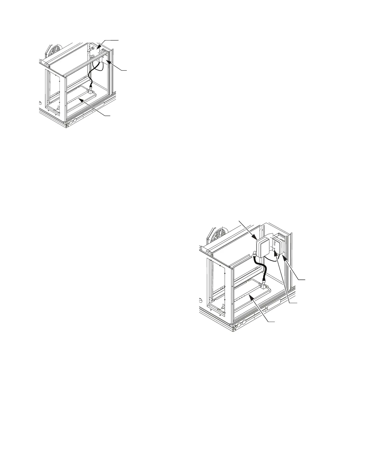
Fig. 38 — Typical Return Air Detector Location
RETURN AIR WITH ECONOMIZER
The sampling tube is inserted through the side plates of the econo-
mizer housing, placing it across the return air opening on the unit
basepan. See Fig. 39. The holes in the sampling tube face down-
ward, into the return air stream. The sampling tube is connected
through tubing to the return air sensor that is mounted on a bracket
high on the partition between return filter and controller location.
The return air sensor is shipped in a flat-mounting location. Instal-
lation requires that this sensor be relocated to its operating location
and the tubing to the sampling tube be connected. See installation
steps.
FIOP Smoke Detector Wiring and Response
ALL UNITS
The FIOP smoke detector is configured to automatically shut
down all unit operations when a smoke condition is detected. See
Fig. 40 for smoke detector wiring.
HIGHLIGHT A
The JMP 3 is factory-cut, transferring unit control to the smoke
detector.
HIGHLIGHT B
The smoke detector NC contact set will open on a smoke alarm
condition, de-energizing the ORN conductor.
HIGHLIGHT C
24v power signal using the ORN lead is removed at the Smoke
Detector input on the Central Terminal board (CTB); all unit oper-
ations cease immediately.
PREMIERLINK AND RTU-OPEN CONTROLS
Unit operating functions (fan, cooling and heating) are terminated
as described above.
Highlight D
On smoke alarm condition, the smoke detector NO Alarm contact
will close, supplying 24V power to the GRA conductor.
Highlight E
The GRA lead at the Smoke Alarm input on LCTB provides a 24v
signal to the FIOP DDC control.
PremierLink
This signal is conveyed to PremierLink FIOPs TB1 at terminal
TB1-6 (BLU lead). This signal initiates the FSD sequence by the
PremierLink control. FSD status is reported to the connected CCN
network.
RTU-OPEN
The 24v signal is conveyed to the RTU-OPEN J1-10 input termi-
nal. This signal initiates the FSD sequence by the RTU-OPEN
control. FSD status is reported to the connected BAS network.
USING REMOTE LOGIC
Five field-use conductors are provided for field use (see
Highlight F in Fig. 40) for additional annunciation functions.
ADDITIONAL APPLICATION DATA
Refer to Factory-Installed Smoke Detectors for Small and Medi-
um Rooftop Units 2 to 25 Tons for discussions on additional con-
trol features of these smoke detectors, including multiple unit co-
ordination.
Fig. 39 — Return Air Sampling Tube Location in Unit
with Economizer
*RA detector must be moved from shipping
position to operating position by installer.
RETURN AIR DETECTOR
SAMPLING TUBE
RETURN AIR
DETECTOR MODULE
(Shipping position
shown)*
CONTROLLER
MODULE
RETURN AIR SENSOR
(Operating Position Shown)
SCREWS (2)
SAMPLE TUBE
CONTROLLER
MODULE

 Loading...


