6
Owner's manual
6. CONSTRAINT COOLING AND QUERY
Constraint Cooling
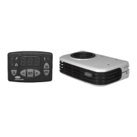
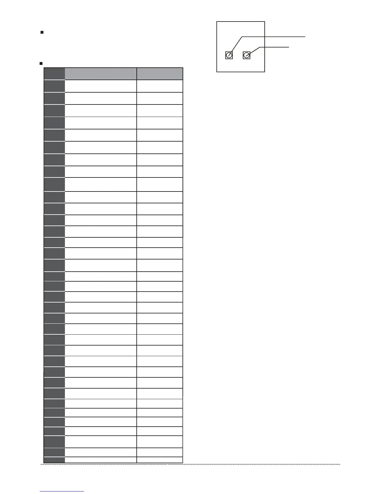
Once pressing the constraint cooling button (see the chart on
the right), all indoor units will be on forced cooling mode and the
wind speed is HIGH).
Fig.6-1
MAIN BOARD
(OUTDOOR UNIT)
Query button
Constraint cooling button
CHECK
COOL
Table.6-1
Usage application of the SW2 spot check
1
2
3
4
5
6
7
8
9
10
11
12
0,1,2,3
8,10,12,14,16,18,20,22
0,2,3,4
13
14
15
16
Outdoor unit address
No. Note Display content (normal display)
Outdoor unit itself capacity
Modular outdoor unit qty.
Operation mode
This outdoor unit actual operation
capacity
T2B/T2 average temp.
T3 pipe temp.
T4 ambient temp.
Available for
main unit
Available for
main unit
Available for
main unit
Capacity
requirement
Capacity
requirement
Actual value
Actual value
Actual value
Actual value
Actual value
Actual value +30
Total capacity of outdoor units
Total requirement of indoor unit
capacity
Total requirement of main unit
corrected capacity
Speed of fan A
Discharge Temp.of Inverter
compressor A
Actual value
Qty.setting of indoor units
Speed of fan B
Discharge Temp.of Inverter
compressor B
Available for
main unit
17
18
19
20
21
22
23
24
25
26
27
28
29
30
31
32
33
----
Actual value
Actual value
Actual value
Check end
Display
value×0.1MPa
0,1,2,3
0,1,2,3
0,1,2,3,4
Opening angle of EXV A
Qty. of Indoor units
Current of inverter compressor A
Heat sink Temp.
Low pressure (reserve)
Current of inverter compressor B
Opening angle of EXV B
High pressure
Qty. of working indoor units
Priority mode
Night noise control mode
Static pressure mode
DC voltage A
DC voltage B
that can communicate
with indoor units
Reserve
34
Times errors cleared
35
Last-time error or protection code
If there is no protection or error,
the panel displays 8.8.8.
7. AFTER-SALE SERVICE
If the air conditioner is operating abnormally, please
unplug it at the mains and contact the after-sales center
or special distributor. For details, please refer to the
attached accessory Consumer Service Instructions.
The display contents as followings:
(1)Normal display: When standby, the high position displays the
address of the outdoor unit, and the low position displays the Qty. of
indoor units that can communicate with outdoor unit .When it’s on, it
will display the rotation frequency of the compressor.
(2)Operation mode: 0-OFF; 2-Cooling; 3-Heating; 4-Constraint
cooling.
(3)Fan speed: 0-stop; 1~15: speed increase sequentially, 15 is the
max. fan speed.
(4)EXV opening angle: Pulse count=display value×8.
(5)Priority mode: 0-heating priority mode; 1-cooling priority mode;
2-Number 63 & the more operating mode first; 3-respond the heating
mode only; 4-respond the cooling mode only.
(6)Night noise control mode:0-Night noise control mode; 1- silent
mode ; 2-most silent mode;3-no priority.
(7)Static pressure mode:0-Static pressure is 0 Mpa; 1-Static
pressure mode is low pressure; 2-Static pressure mode is medium
pressure; 3-high static pressure mode is high pressure.
 Loading...