ADJUSTMENTS
Checking For Correct Operation of the
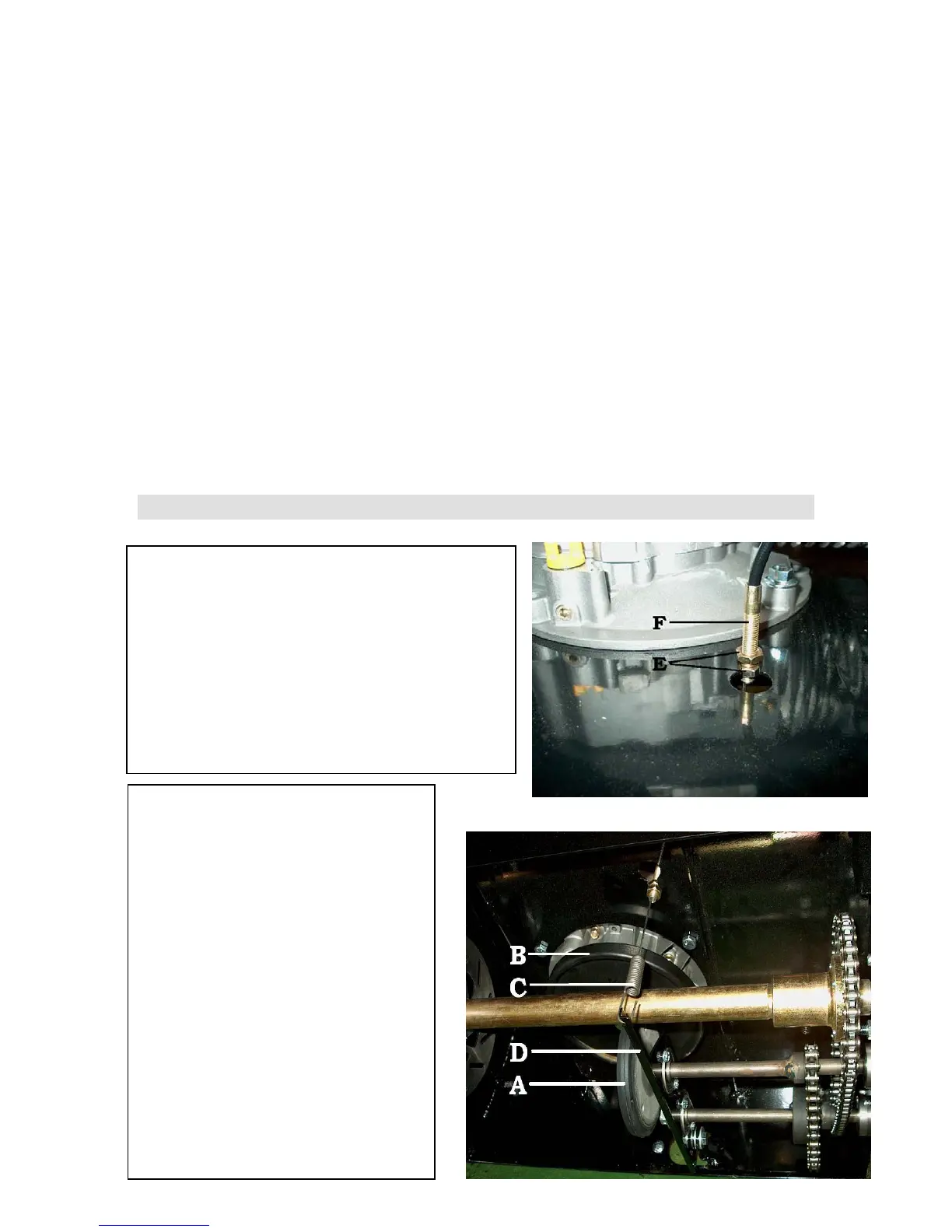
Throttle (Fig. 3-1 and 3-2)
With no pressure on the throttle pedal, there
should be approximately 1/16” of space between
the rubber molded disc (A) and the inertia
wheel. (B). When the throttle pedal is depressed,
the throttle cable (C) pulls the throttle actuating
arm (D) up causing the rubber molded disc (A)
to make contact with the inertia wheel (B).
Fig. 3-1
Adjusting the Throttle Cable
(Fig. 3-1 and 3-2)
Remove the bottom cover of the rear
end. Loosen the throttle cable
retaining nuts (E). Insure that the
throttle cable (C) is attached to the
throttle actuating arm (D) as shown.
Adjust the position of the throttle
cable sleeve (F) so that, with no
pressure on the throttle pedal, there is
1/16” of space between the rubber
molded disc (A) and the inertia wheel
(B). Tighten the throttle cable
retaining nuts (E). Check to insure
there is a 1/16” of space between the
rubber molded disc (A) and the
inertia wheel (B). Remove the
ttom cover of the rear end.
14