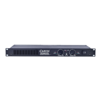
DCM1000
∞
50
30
22
19
17
15
13
12
11
10
9
8
7
6
5
4
3
2
1
0 dB
∞
50
30
22
19
17
15
13
12
11
10
9
8
7
6
5
4
3
2
1
0 dB
8 OHM 325W/CH - 1200W BRIDGE
4 OHM 600W/CH - 2000W BRIDGE
2 OHM (MIN) 1000W/CH
120-240VAC 50/60Hz 1000VA
BRIDGE
OUTPUT
SPEAKONS™ ACCEPT 1/4 INCH JACKS
INPUT
THRU INPUT INPUT THRU
GND PARALLELLIMITERBRIDGE
LIFT
ONLY
BRIDGE
1
2
1
2
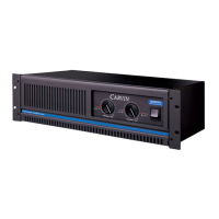
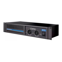
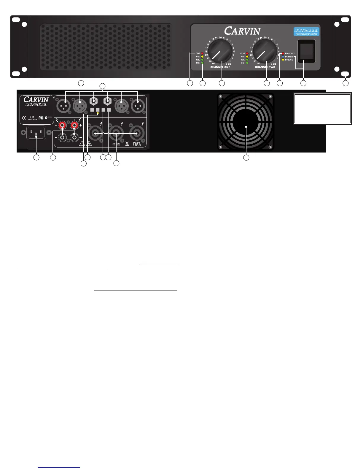
FRONT PANEL
1. MOUNTING
Sturdy one piece 12 gauge steel face plate accommodates standard 19” rack installation. The rack mount-
ing holes are designed on ISO standard spacing. Four 10-32x.5” phillips machine screws are normally
used to secure the amp. Rear support brackets are not required.
2. POWER SWITCH
Check the power amp AC making sure the rear plug is fully inserted before engaging the power switch.
The blue POWER LED indicates that all circuits are properly powered up.
3. PROTECT RED LED INDICATOR
The RED PROTECT LED provides the operator with information about the status of the amplifier. The
PROTECT LED can come on under 3 different conditions (when this happens, both channels are muted
and the speaker relays disconnect the speakers);
1) During power-up, the amplifier stays in a muted state for approx. 3 sec until it determines that
everything is functioning normally (no output shorts or over temp conditions).
2) The RED PROTECT LED will illuminate when the output load draws excessive current or a direct
short is detected caused by a shorted speaker cable or speaker system. Reset this condition by
turning the amp off for two seconds and then on again. Check for shorted cables and that the total
speaker impedance is not below 2 ohms per channel - 4 ohms bridged (DCM1540L - 4 ohms per
channel/ 8 ohms bridged).
3) Overheating is usually determined when the amp stops in the middle of a performance and the RED
PROTECT LED comes on. If this is the cause, leave the amp on for the fan to cool the amp down.
The amp will automatically reset within 3 minutes. The PROTECT LED will turn off when ready.
Check for the following conditions; a) The rear intake air is not restricted, b) The intake air is not
extremely warm, c) The front exhaust vents are not restricted, or d) No excessive speaker load (try
other speakers or remove speakers if you have more than one connected to each channel).
Power supply protections are not indicated by the protection LED, but by the power turning off completely.
If the protected state is a thermal power supply issue or an over current power supply issue, the power
supply with reset it self and go through the same turn on cycle as when first turned on.
4. CHANNEL LEVEL CONTROL
A precision input LEVEL attenuator is used to adjust the volume levels. To deliver the amps maximum
power without reducing the headroom of the signal source, the level controls should be turned full on.
For multi-speaker systems, the volume levels can be used to match loudspeakers with different output
sensitivity levels and room locations.
5. CHANNEL SIGNAL INDICATOR, 40% & 80% OUTPUT
You have a 3 meter segment per channel to indicate levels. The green SIGNAL LED indicator will start
to flash when there is a low input signal (-30dBµ). The 40% and 80% LED’s will light solid when output
power has reached 40% and 80% levels.
6. CHANNEL CLIP INDICATOR
The RED CLIP LED indicators flash when each channel has reached its maximum output. Occasional
flashing caused by low frequency peaks are difficult to prevent and will not harm speakers capable to
handle the amplifiers output. However, consistent flashing (excessive clipping/square wave) will damage
speakers if not reduced. This does not cause damage to the amp.
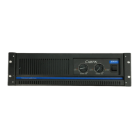
7. COOLING VENTS/FAN
Upon rack installation, the rear of the amp must be fully exposed to room temperature air. The surrounding
air should not be warmer than 120° with full loading and heavy usage, or the thermal protection could
active early. The front cooling vents are not to be restricted. Air flows from back to front. The use of external
fans need to flow the same direction or the amplifier will starve for air and thermal off.
2 14
5
67
7
15
9
14
WARNING
This product produces high
sound pressure levels that could
damage your hearing. Use with
caution.
FRONT & REAR PANEL CONTROLS
8
13
34
1011
12
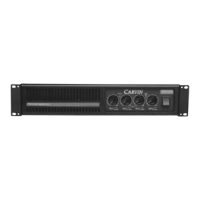
REAR PANEL
8. CHANNEL INPUTS
The XLR balanced inputs will help reduce signal interference and allow longer cable runs from your
signal source (mixer, etc). Because this is a balanced input, the gain will be 6 dB higher than using an
unbalanced 1/4” cable on the 1/4” TRS input jacks. XLR pin configuration: Pin 1: Grounded through the
GROUND LIFT switch, Pin 2: positive balanced signal, Pin 3: negative balanced signal. The THRU XLR
connector passes the signal out for connection to another amplifier’s input.
The 1/4” TRS jacks are balanced and designed to receive unbalanced input signals. Balanced signals
coming into this jack should be wired with the connector’s tip going to signal + and the connector’s ring
to signal -. The connector’s sleeve is tied internally to ground through the GROUND LIFT switch.
9. PARALLEL “Y” INPUTS
The rear PARALLEL switch connects both channels together from either input. This eliminates Y adapter
cables. This feature is used to “daisy chain” one piece of equipment to another. Just plug into the unused
INPUT (TRS or XLR) and it will become the output for other equipment.
10. INPUT GROUND LIFT
Systems can be connected in such a manner as to cause a “grounded loop” with the inputs, which results in
audible hum. The input GND LIFT switch (TRS & XLR) on the rear panel will help eliminate this problem.
11. LIMITERS
To activate the LIMITERS, engage the rear limiter switch. The built-in limiters are recommended to hold
down peaks that could cause clipping. To check the effectiveness of the limiters, run the amplifier to the
point where clipping begins. Then engage the limiters and listen/watch for the reduction of the distortion
and clipping. If the distortion stops, you can try to turn the channel up for more power until distortion is
heard. The lower bass frequencies are most affected. WARNING: Do not check in an environment where
the sound level could damage your ears! Limiters only affect the signal if the amplifier has entered clipping
so it is best to have the limiters engaged at all times to protect the speakers from excessive clipping.
12. BRIDGE MODE
With your amp off, push “in” the rear (recessed) BRIDGE switch then make your connections to either the
center bridge Speakon™ or the RED binding posts (ch 1 is + and ch 2 is-). In bridged mode, the ampli-
fier channels are out-of-phase from each other. Accidental pressing of the switch will cause damage or
improper operation. WARNING: No other speaker connectors or binding posts may be used at the same
time! Use channel 1 INPUT and LEVEL for bridge mode. Channel 2 is not used, except for parallel to another
amplifier (see 9 PARALLEL). The minimum speaker impedance is 4 ohm (8 ohm for the DCM1540L) .
CAUTION: The power developed by bridging your amp can destroy most speakers.
13. SPEAKER 1/4” AND SPEAKON™ COMBO OUTPUTS
The speaker connectors feature a combination of both 1/4” SPEAKER jacks for low power applications
and Speakon™ connectors for high power application. Secure the Speakon™ connection by turning to
the right to the lock position. The center Speakon™ is for the “Bridge” output only. Turn the amp off
before connecting your speakers.
14. SPEAKER BINDING POSTS
For wire (banana connectors), use the rear BINDING POSTS to connect your speakers. Wire sizes up to 7
gauge (50 amps) can be inserted into the binding post “side holes”. Larger cable can be used with “banana”
plugs which plug into the end of the binding posts. Binding posts are spaced on ISO standards. Use the two
center RED binding posts to BRIDGE speaker connections (see 12 BRIDGE MODE).
15. AC POWER Your amp is designed to auto switch to either 120V 60 Hz or 240V 50Hz. The volt-
age range for 120V is 95V to 132V and for 240V is 195V to 255V. The rear heavy-duty AC receptacle
will accept a universal grounded AC cord. Be sure to check your power source before plugging into a
grounded (3 prong) outlet. Firmly push the AC cord all the way into the receptacle or the amp will not
function. WARNING: Never defeat the grounded connection or electrocution may result! FUSE: The
fuse is located within the main chassis near the AC connector on the PC card. Normaly if the fuse fails,
the amp will require service. See specifications chart for fuse values. NOTE: Each amp will require a
dedicated circuit breaker for the amp to achieve its full output.
 Loading...