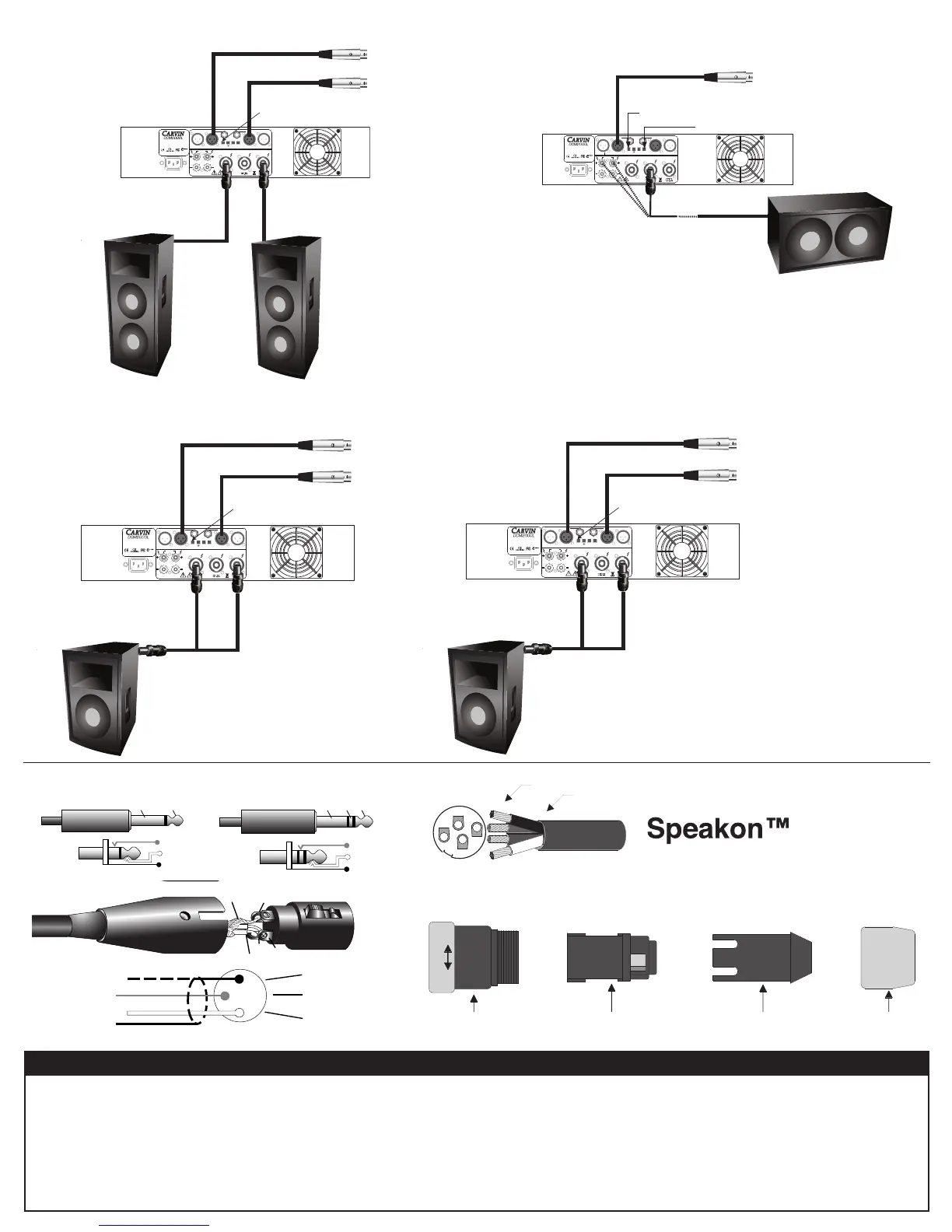
TYPICAL STEREO SETUP (OR MONO BI-AMP)
PARALLEL switch OFF (OUT).
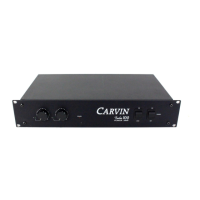
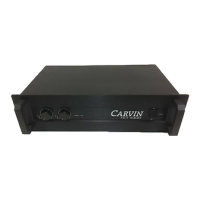
8 OHM 325W/CH - 1200W BRIDGE
4 OHM 600W/CH - 2000W BRIDGE
2 OHM (MIN) 1000W/CH
120-240VAC 50/60Hz 1000VA
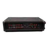
BRIDGE
OUTPUT
SPEAKONS™ ACCEPT 1/4 INCH JACKS
INPUT
THRU INPUT INPUT THRU
GND PARALLELLIMITERBRIDGE
LIFT
ONLY
BRIDGE
1
2
1
2
To signal socket XLR or 1/4" 2 or 3 cond. shielded
Activate the BRIDGE switch
(IN). Control the level by Ch 1
(Ch 2 does not function.)
Ch 1 Input
Single speaker or
system connected
in BRIDGE mode.
Minimum imp. 4
W
Use either the
Bridged Speakon™
connector or the
binding posts. No
other connections
can be used while in
Bridged mode.
8 OHM 325W/CH - 1200W BRIDGE
4 OHM 600W/CH - 2000W BRIDGE
2 OHM (MIN) 1000W/CH
120-240VAC 50/60Hz 1000VA
BRIDGE
OUTPUT
SPEAKONS™ ACCEPT 1/4 INCH JACKS
INPUT
THRU INPUT INPUT THRU
GND PARALLELLIMITERBRIDGE
LIFT
ONLY
BRIDGE
1
2
1
2
Right Full Range
For (stereo) the PARALLEL
switch must be OFF (OUT).
Left (Mono) Full Range
Ch 1 Left
Ch 2 Right
BRIDGE switch
must be OFF (OUT).
BRIDGED MONO
SHIELD
-NEG.
3
1
2
GND
+ SIGNAL (BAL.)
Twist-Lok
Housing
Contact
Insert
Cable
Clamp
Securing
Hub
• Connection Configuration:
Black (1+) / positive
White (1-) / negative
Red (2+) / positive
Green (2-) / negative
• Solder wires in contacts or use hex screws provided.
• Slip "Securing Hub" then "Cable Clamp" over cable before attaching wires.
1+
1-
2+
2-
Solder tinned wires 1/4"
Strip cable insulation back 3/4"
Sleeve
Ring
Neg.
Tip
Pos.
TRS 1/4” Balanced
Tip-Ring-Sleeve
TS 1/4” Unbalanced
Tip-Sleeve
TipSleeve
Ring
Tip
XLR
Tip
Ground
Ground
Ring
- SIGNAL (BAL.)
HELPFUL HINTS
6) DEDICATED CIRCUIT BREAKER: Each amp will require
a dedicated circuit breaker for its full output. There will be
a sustained loss of power if the AC voltage falls below the
rated 120V or 230/240V input. Normally a 2000w amp or
higher would require its own 20 amp circuit to deliver its
full power at 2 ohms/channel or 4 ohms bridged.
1) NO SOUND FROM CH 2: The rear (recessed) BRIDGE
switch has been inadvertently pushed in.
2) STEREO CHANNELS SOUND THE SAME: The rear
PARALLEL switch has been inadvertently pushed in.
3) NO HIGH FREQUENCIES: Tweeters or midrange drivers have
been damaged or blown from feedback or to much power.
4) SYSTEM HUM: Switch the rear GND LIFT switch IN to
reduce hum.
5) POOR SOUND (BASS): The speaker systems are wired out
of phase to each other. To correct, check polarity and if nec-
essary reverse the wires on one speaker connector only and
your sound, especially the bass will improve.
8 OHM 325W/CH - 1200W BRIDGE
4 OHM 600W/CH - 2000W BRIDGE
2 OHM (MIN) 1000W/CH
120-240VAC 50/60Hz 1000VA
BRIDGE
OUTPUT
SPEAKONS™ ACCEPT 1/4 INCH JACKS
INPUT
THRU INPUT INPUT THRU
GND PARALLELLIMITERBRIDGE
LIFT
ONLY
BRIDGE
1
2
1
2
PARALLEL
switch must be OFF (OUT).
Ch 1 Low Frequencies
Ch 2 High Frequencies
BRIDGE switch
must be OFF (OUT).
4-pin Speakon
2-pin
2-pin
LEFT
RIGHT
STEREO BIAMPING MUST USE AN ELECTRONIC CROSSOVER OR SPEAKER MANAGEMENT SYSTEM TO SEPARATE HIGH AND LOW FREQUENCIES
 Loading...