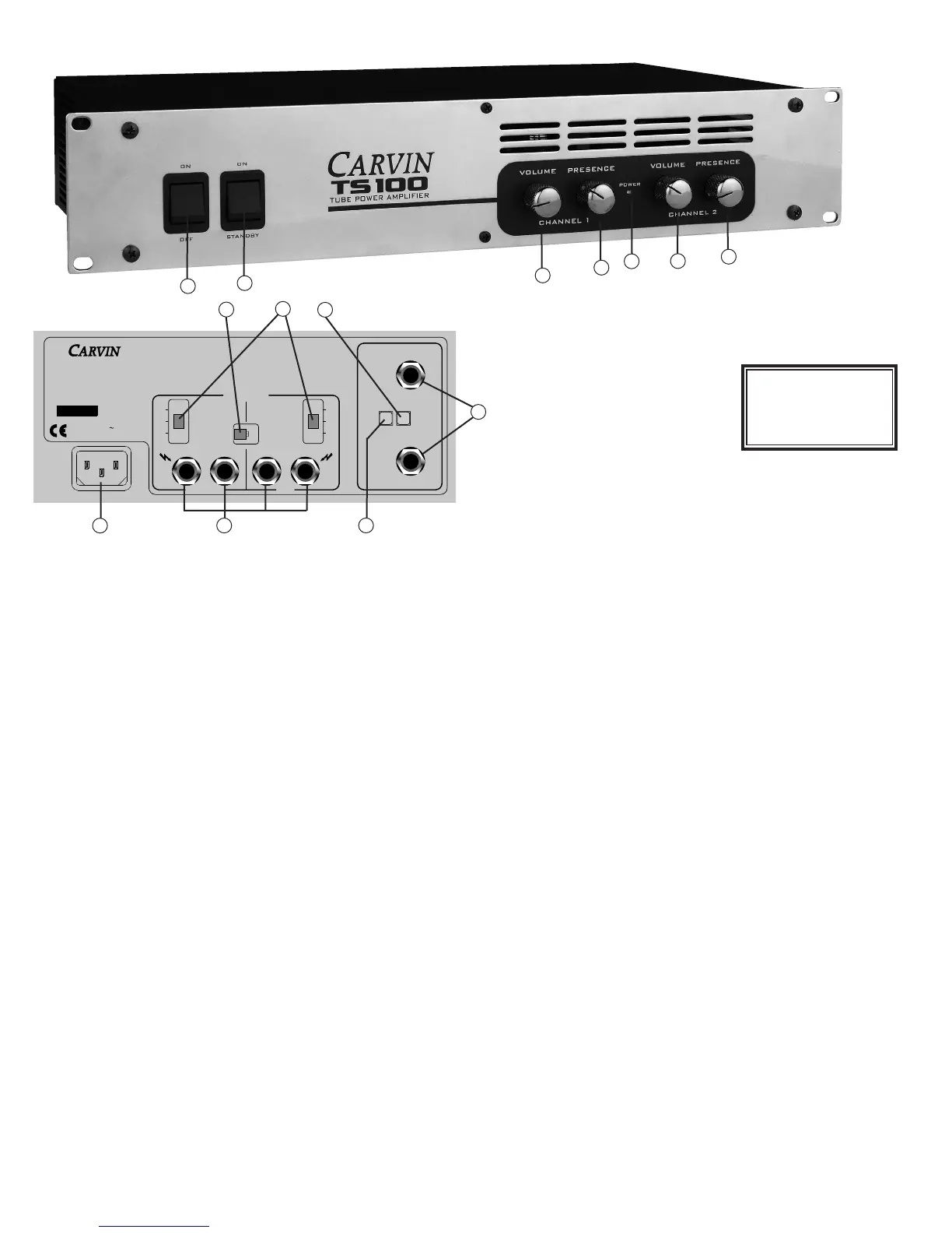
FRONT & REAR PANEL CONTROLS
WARNING
This product produces high
sound pressure levels that
could damage your hearing.
Use with caution.
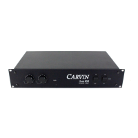
FRONT PANEL
1. POWER
Turns on power to the unit.
2. STAND-BY
Turns on high voltage to the tubes. Usually, this switch should be off when the
amp is initially powered on until the tube filaments warm up (30 seconds, or
more). The amplifier should be switched to stand-by whenever the amp will not
be used for a short amount of time (like a set break) to increase tube life.
3. VOLUME
Controls the amount of signal sent to the power amp, which controls the output
level. Start with this control all the way down. Make sure the preamplifier is
connected and turned on and it’s level turned up. Bring the amplifier volume up
to the desired loudness. Experimentation will be needed to get the correct volume
balance between the preamplifier output and the amplifier output level. The ampli-
fier should be turned up at least one half with the knob indicator lines running
vertical. Note: When the amp is in bridge mode, Channel 1 will be the master
volume control - Channel 2 volume will not function.
4. PRESENCE
Controls the amount of clarity or crispness in the 6kHz range. When this con-
trol is all the way down, the frequency response will essentially be flat. Bringing
this control up will create a "bump" in the upper frequencies. Note: In bridge
mode, track both Channel 1 and 2 presence knobs to the same position.
5. POWER LED
The blue LED indicates that the power supply has been turned on.
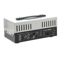
REAR PANEL
6. AC POWER AND FUSE
The detachable AC power cord is designed to operate with one type of voltage.
Check the rear label above the AC connector for the proper voltage. Make sure
the AC cord is securely inserted. If not, the power amp could become intermit-
tent. Plug the AC cord into a grounded 3-prong power source. No attempt should
ever be made to defeat, or use the amp without the ground connected. The fuse
is internal to the unit. Replace only with the same type and rating.
7. SPEAKER OUTPUT JACKS
Two 1/4" speaker output jacks are provided for each channel. Each pair of jacks
are wired in parallel. Set the impedance switch accordingly for each channel.
The total impedance for each channel should not be less than 4Ω. Note: when
in bridge mode, only Channel 1 output jacks will work and the impedance switch
for each channel must set to half of the total speaker load impedance.
8. IMPEDANCE SELECTION SWITCH
Use the impedance switch to match the speaker load to the output transformers.
This switch should be set to the equivalent load connected to the speaker out-
puts of each channel or loss of output power will result. The speaker output jacks
are in parallel so if two 8Ω speakers are connected the total impedance would be
4Ω for that channel. Likewise if two 16Ω speakers are used, then move the imped-
ance switch to 8Ω.
Note: when in the bridge mode, the impedance switch for each channel must
be set to one half the total load impedance. This means for two 16Ω or one 8Ω
speaker, set each channel to 4Ω. If you are using one 16Ω speaker, then set each
channel to 8Ω. The minimum impedance for the TS100 in bridged mode is 8Ω.
9. BRIDGE/STEREO SWITCH
For mono 100W output, set this switch to "BRIDGE". If using the bridge mode,
use the speaker outputs from Channel 1 only and use the Channel 1 volume con-
trol. If stereo operation is desired, set to "STEREO" mode. In this mode, both
channels operate as separate 50W amplifiers and each channel’s controls can
be adjusted independently. Make sure the impedance switch is properly selected
for each channel.
10. GROUND LIFT SWITCH
Many times amplifiers and preamps are connected in such a manner as to cause
a grounded loop with the inputs which results in audible hum. To activate, press
this switch in to lift the ground. If the hum has not been reduced, then try installing
a Carvin MTF55 “Ground lifter” between the amplifier input and the signal.
11. PARALLEL INPUTS SWITCH
Pressing this switch in will split the signal that is plugged into the Channel 1
input to both Channel inputs. Channel 2 input will no longer function when this
switch is activated.
12. CHANNEL INPUTS
A 1/4" unbalanced jack is used to deliver signal to each of the amplifiers chan-
nels. If it is desired to use the amplifier for home audio, an RCA to 1/4" adapter
(Carvin #AD66) will most likely be needed. The amplifier can accept a wide range
of signal levels.
7
10
12
8
9
11
6
1
2
5
4
3
3
4
 Loading...