MIDI
FOOTSWITCH
FS22
EFFECTS
LOOP
SEND
RETURN
L
R
OUTPUT 1
CABINET VOICED
L
R
OUTPUT 2
ALTERNATE
INPUT
R
L
(MONO)
PHONES
MADE
AUS
INTHE
INTERNAL
FUSE
125VA
90-250 VAC
50-60HZ
SERIAL NUMBER
x x x x x x
THRUIN
+4 +4
TN100
GND
LIFT
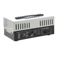
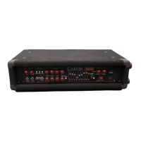
Switch to STEREO position
PARALLEL switch should be OUT
STEREO SETUP
Set each IMPEDANCE switch to match each speaker cabinet
MIDI
FOOTSWITCH
FS22
EFFECTS
LOOP
SEND
RETURN
L
R
OUTPUT 1
CABINET VOICED
L
R
OUTPUT 2
ALTERNATE
INPUT
R
L
(MONO)
PHONES
MADE
AUS
INTHE
INTERNAL
FUSE
125VA
90-250 VAC
50-60HZ
SERIAL NUMBER
x x x x x x
THRUIN
+4 +4
TN100
GND
LIFT
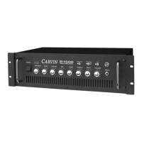
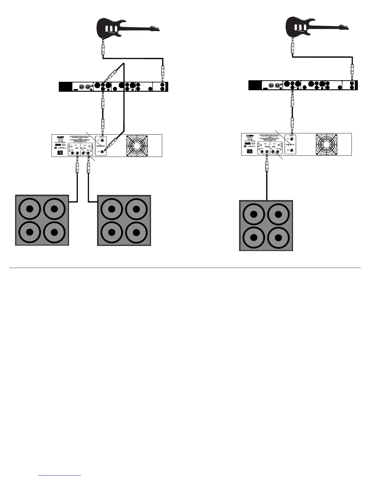
Switch to BRIDGE position
PARALLEL switch can be IN or OUT
MONO SETUP
Set each IMPEDANCE switch to
HALF of total speaker impedance
(Note: If a mono source is used, use CH 1
input and switch PARALLEL switch IN)
POWER TUBE BIASING
(Note: Biasing should be left to a qualified technician due to the fact that lethal
voltages near 500 volts are present inside the amplifier).
The TS100 can be set up to use either EL34’s or 5881’s (6L6GC) in each
channel. If different tube type are used in each channel, the amp should only
be used in STEREO mode
Inside the amplifier, on the component side of the power tube printed cir-
cuit card, are switches to select the tube type for each channel. Above those
switches are markings that indicate the different tube types. Bias potentiometers
are also near those switches for fine-tuning. Each side of the amplifier must
be biased with ALL four power tubes installed.
a) Remove from the printed circuit board the red wires connecting from the
output transformers to QC2 and QC16.
b) Two milliamp meters will be needed. Insert a milliamp meter in series
with each of the red wires to the printed circuit board. Current can now be
measured through both of the output transformers while no input signal is
present. Make sure the leads don’t touch anything such as the chassis, each
other, or you- VERY HIGH VOLTAGES ARE PRESENT!
d) Make sure the bias select switch is in the correct position for the tube
type and the meters are set to “mA” or milliamps.
e) Power up the amplifier – switch the stand-by switch on. Adjust the bias
pots accordingly to obtain a 50mA reading on each of the milliamp meters.
Leave the amp on for a few minutes making sure the readings don’t change.
Turn the amp off, leaving the standby switch on and let the residual high volt-
age bleed down. Remove the milliamp meters from the series connection
and re-attach the red wires directly to QC2 and QC16 again. The amp is now
correctly biased. CAUTION: The power supply capacitors will remain
"charged" for a period of time after the amp has been turned off with volt-
ages near 500 volts.
(If only volt meters are available, an alternate method of biasing can be used
by substituting 1Ω, 1/2 watt resistors where the milliamp meters would be
as described above. The voltage across each resistor should read 50mV
corresponding to 50mA. The rest of the procedure outlined above is the same.)
STEREO SETUP
MONO SETUP

 Loading...