SECTION 58 - DRIVELINES - CHAPTER 3
58-17
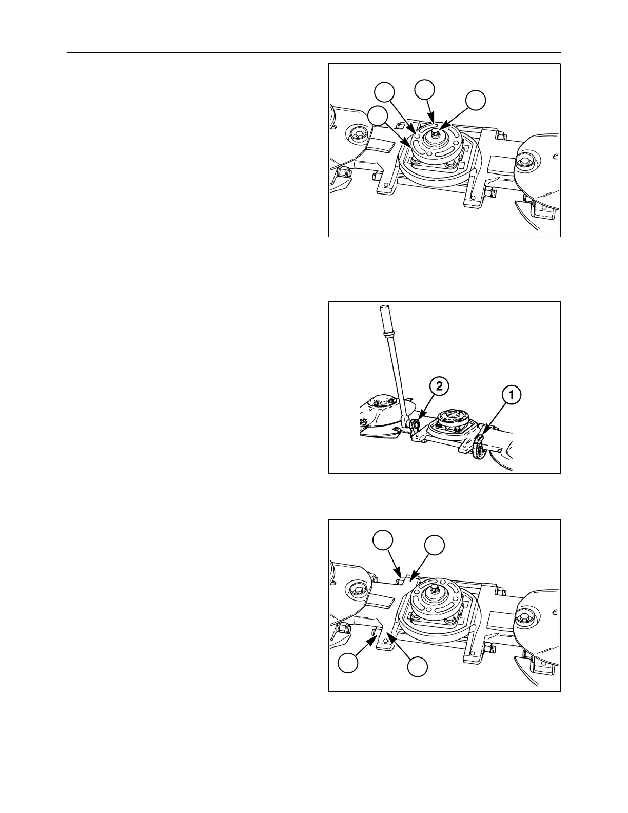
Slide the disc hub, 1, onto the top cap shaft; if it is
not perfectly timed to the adjacent discs, remove
the disc hub, rotate it 90° and reinstall it. Continue
to do this until the disc hub is properly timed; one
of the four positions will provide correct timing.
NOTICE: With the adjacent discs positioned at 90
°
,
the breather, 3, should be completely visible through
the disc hub bolt hole, 4, when the hub is properly
timed.
After determining the correct position, apply a thin
coating of grease to the seal lip and sealing
surface on disc hub, and carefully slide disc hub
onto shaft past seal. If the module has a hex head
cap screw, discard this cap screw and install a
new 12-point cap screw. Apply a small amount of
silicone sealant to the end of the disc hub
retaining bolt, 1, and torque it to 224 N⋅m (150 lb
ft) or turn the bolt 90° after the bolt has contacted
the washer.
7. The tie bolts which connect the cutterbar together
are torqued using the degree method of torquing,
which requires a special procedure. Install
holding tools #FNH01221-2, 1, onto the nuts on
one end of each tie bolt. Then, using tool
#FNH01221-3, 2, with a torque wrench, torque
both tie bolts to 50 lb ft.
NOTICE: Always torque or turn the rear tie bolt first.
8. Use a marker or scribe to mark the front and rear
nut positions, 1, Figure 38, relative to spacer, 2.
Using wrench #FNH01221-3 and a 3/4 inch
breaker bar, turn each nut 1/2 turn at a time to
achieve one full turn on each tie bolt, starting with
the rear tie bolt first. This will give a total torque on
thetieboltof50lbftplus1turn,foraclamping
force of 35,000 to 37,000 Ibs.
NOTICE: It may be necessary to use a cheater bar
to obtain enough leverage to complete tightening the
tie bolts. Ensure the mower is adequately secured to
prevent tipping unit off its jackstand.
9. Remove special tools from the cutter bar; it may
be necessary to use a hammer to knock the
holding tools #FNH01221-2 off of the nuts.
10. Reinstall the rock guard, skid shoe and disc on the
replacement module.
19986023
1
2
4
3
35
36
19986023
1
2
2
1
37