SECTION 58 - DRIVELINES - CHAPTER 3
58-16
It may be necessary to determine the direction of
rotation of a replacement module prior to
installing it in the cutter bar. Note that the pinion
end of the lower module shaft has a groove, 1, in it
to determine which side of the module the pinion
gear is on; this affects direction of rotation. If the
groove (pinion) is on the right side of assembled
module, module will rotate clockwise, while a
module with the groove (pinion) on the left will
rotate counter- clockwise.
4. Slide the cutter bar together so that the other
connecting shaft splines into the pinion shaft, and
the spacer aligning dowels engage the holes in
the disc module. Ensure that the discs on either
side of the replacement module remain timed to
each other.
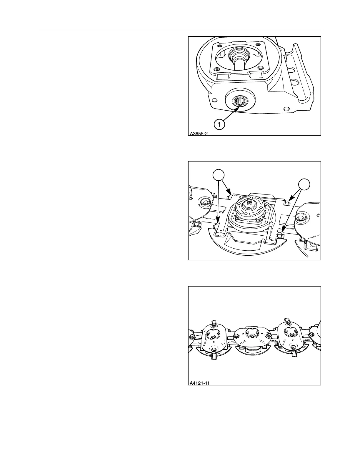
5. Install the nuts, 1, onto the tie bolts, and tighten
finger tight, ensuring that the tie bolt threads
protrude out of the nuts on both ends for full
thread engagement in the nuts.
6. The replacement module must be timed to the
rest of the cutter bar by properly positioning the
disc hub on the top cap assembly. The discs are
properly timed when they are 90° apart, as
shown. The disc hub and top cap shaft splines are
randomly cut, with no index marks.
32
1
1
33
34