SECTION 58 - DRIVELINES - CHAPTER 3
58-27
Installation
1. Prior to reassembly, remove the connecting shaft
from the spacer, and apply lubricant to both ends
of the shaft. Reinstall the connecting shaft.
2. Slide the drive module up against the spacer so
that the connecting shaft splines into the pinion
shaft, the tie bolts are properly positioned, and the
drive module housing fits onto the aligning dowels
on the spacer.
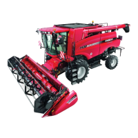
NOTICE: If the mounting holes, 1, are elongated, the
drive module should be replaced.
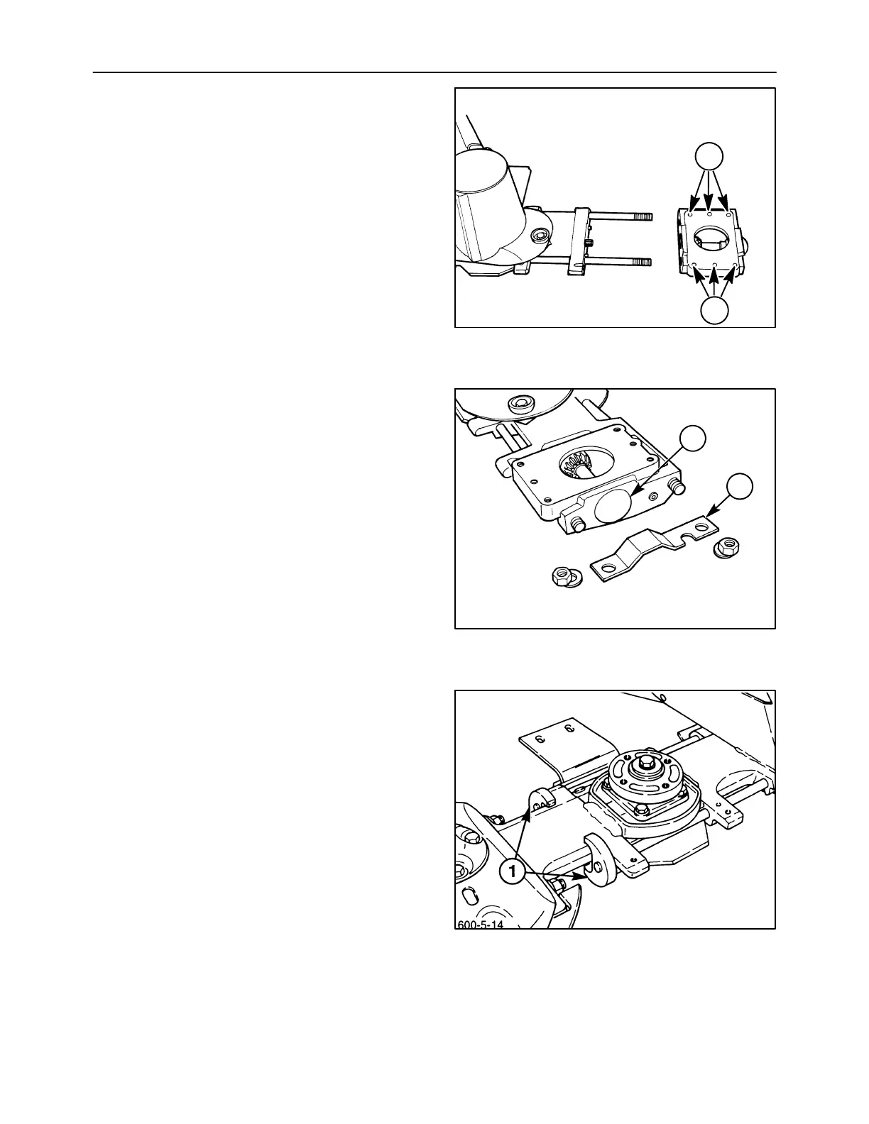
3. Install the guard, 1, over the tie bolts to protect the
dust cap, 2, from being knocked off by field debris,
and install the flat washers and nuts.
4. The tie bolts which connect the drive module and
#1 disc module to the cutter bar are torqued using
the degree method of torquing, which requires a
special procedure. Ensure that the holding tools
#FNH01221-2, 1, are still installed on the tie bolt
nuts at the #1 disc module, and torque the nuts to
68 N⋅m (50 lb ft).
NOTICE: Always torque or turn the rear tie bolt first.
600-5-2
1
1
58
600-5-3
1
2
59
60