SECTION 58 - DRIVELINES - CHAPTER 3
58-28
5. Use a marker or scribe to mark the nut position
relative to the spacer. Using wrench
#FNH01221-3 and a 3/4 inch breaker bar, turn
each nut 1/2 turn at a time to achieve 1-1/2 turns
on each tie bolt, starting with the rear tie bolt first.
This will give a total torque on the tie bolts of 50 lb
ft and 1-1/2 turns.
NOTICE: It may be necessary to partially torque the
tie bolts, complete assembly of the cutter bar back
onto the mower, and then use a cheater bar to obtain
enough leverage to complete tightening the tie bolts.
Remove the special tools from the cutter bar; it
may be necessary to use a hammer to knock the
holding tools #FNH01221-2 off of the nuts.
6. Reinstall the disc and rock guard onto the #1 disc
module.
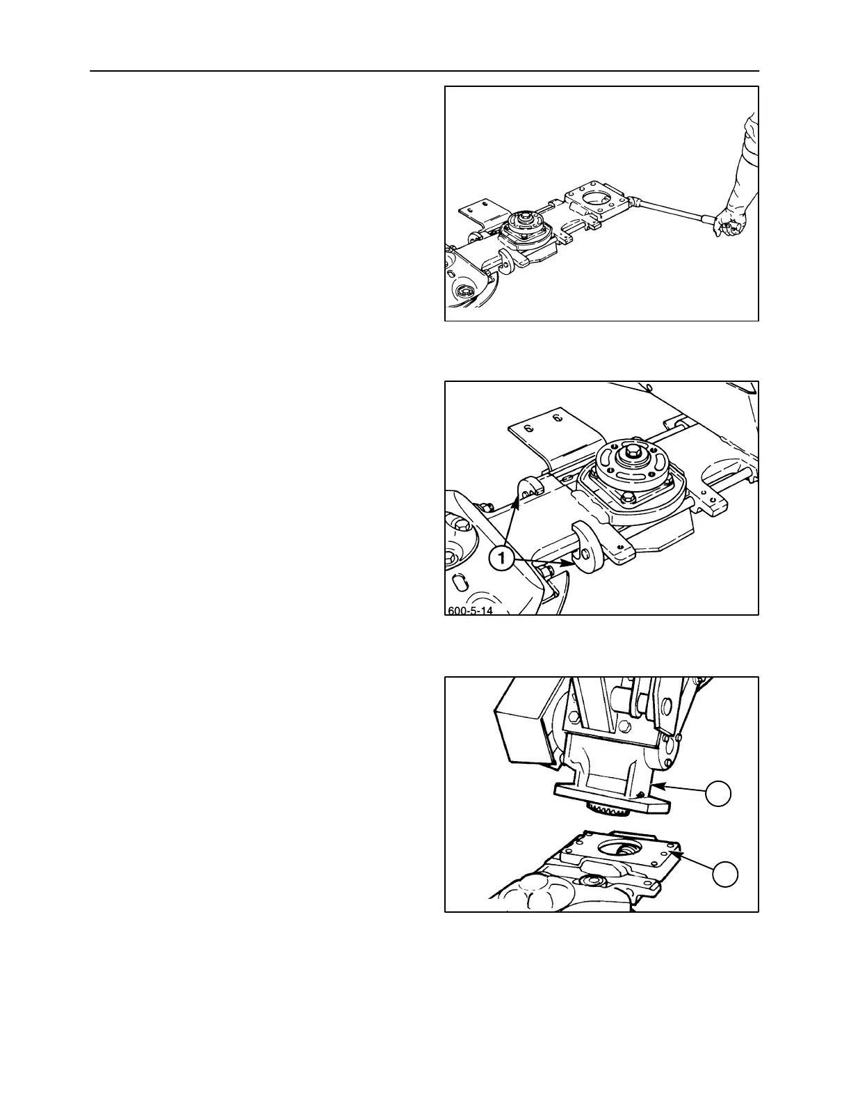
7. Apply a thin coat of sealant to the entire surface of
the drive module, 1. Position the cutter bar under
the bevel gearbox, and use the mower lift cylinder
to carefully lower the gearbox, 2, down onto the
drive module. Ensure that the pilot shoulder on
the bevel gearbox fits into the bore on the drive
module, and the gears mesh together.
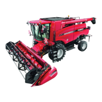
NOTICE: It will be easier to position the gearbox if a
second person pulls on the end of the canopy
support to keep the bevel gearbox level while it is
being lowered.
600-5-16
61
62
600-5-3
1
2
63