SECTION 58 - DRIVELINES - CHAPTER 3
58-29
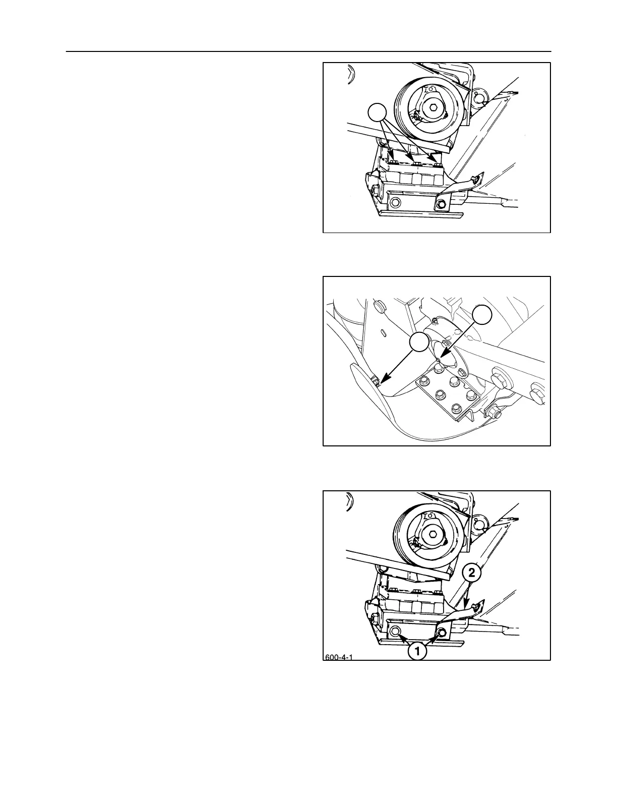
Apply a locking compound to the threads, and
install the three cap screws, 1, to secure the rear
of the bevel gearbox to the drive module. Tighten
the cap screws snugly, but do not torque at this
time.
8. Slide the front lip of the inner skid shoe, 3, on over
the front of the bevel gearbox and drive module.
Apply a locking compound to the threads, and
reinstall the three cap screws, 1, but do not tighten
at this time. Position the inner shield, 4, between
the #1 disc and the canopy support. Attach the
inner shield and pipe support to the front of the
skid shoe using a carriage bolt, 2, and flange nut.
9. Install the two cap screws, 1, and lock washers to
secure the rear of the inner skid shoe to the drive
module; position the inner shield mounting
bracket, 2, under the right cap screw. Tighten the
two rear cap screws, 1, to 83 113 N⋅m (lb ft). After
the two rear cap screws are tightened, torque the
three front cap screws, 1, Figure 64, and the three
rear cap screws, 3, to 159 N⋅m(117lbft).
10. Complete tightening of the tie bolts to 50 lb ft and
1-1/2 turns of torque, if this was not finished
previously.
600-4-1
1
64
19990604
1
2
65
66