SECTION 00 -- GENERAL INFORMATION -- CHAPTER 1
00-11
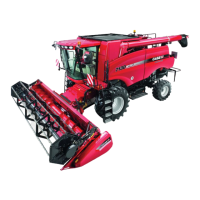
1. Clean all paint or rust from the hitch pins.
2. Attach the plate on the end of the check chains to
the inner or outer end of frame hitch pins, 1, as
required to clear obstructions on the tractor. If
installing on the outer end of the hitch pins, install
the check chain plates before attaching the
tractor lower links.
3. Back the tractor to the mower and attach the lower
links, 2, to the outer end of the frame hitch pins.
Secure the links with linchpins. Install the
linchpins from the top down.
NOTICE: Attach the tractor lower links to the outside
pins only; do not attach the lower links to the pins in-
side the mower frame or damage to the mower PTO
drive shaft could occur.
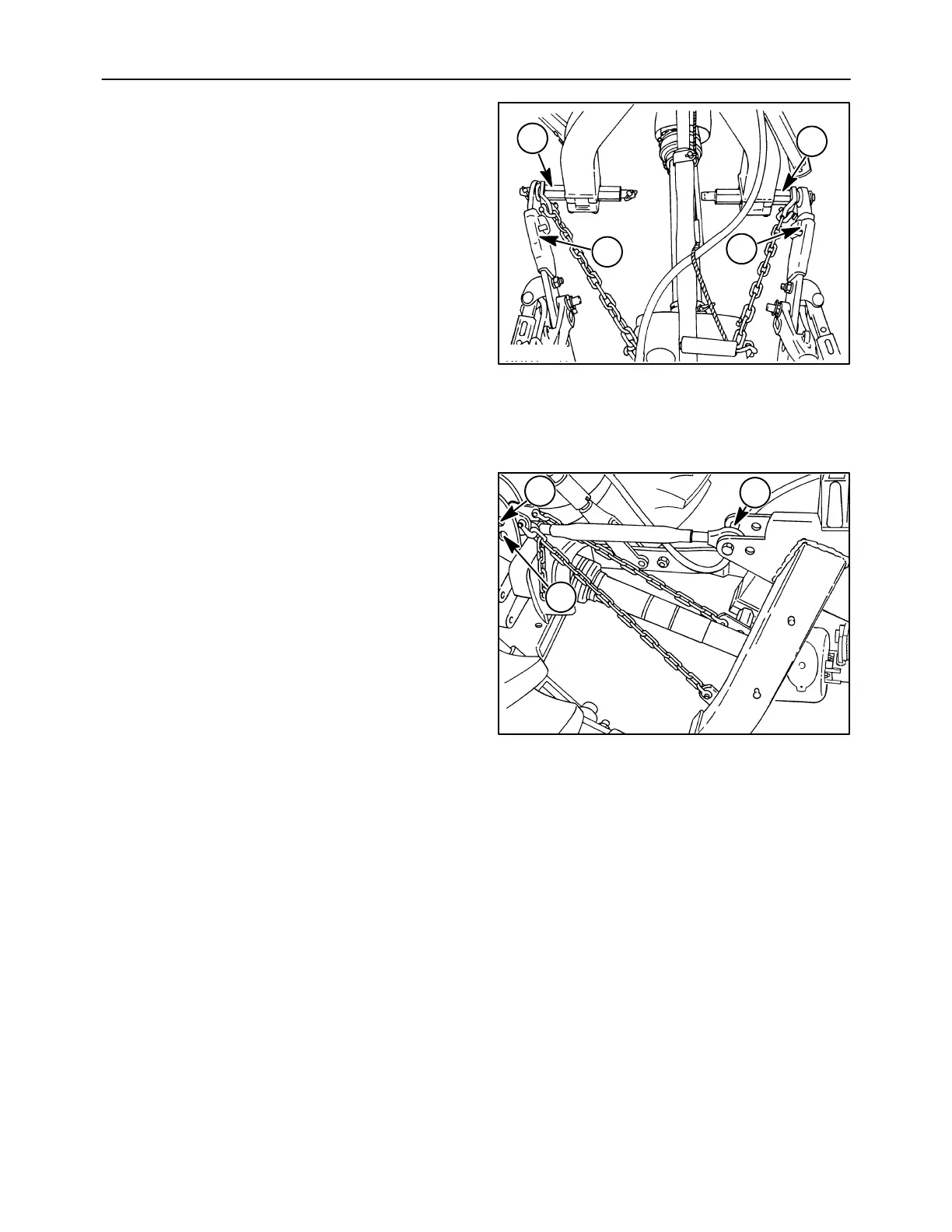
4. Attach the top link to the tractor, 1, using the pin
provided with the tractor top link.
5. Attach the top link to the mower, 2, in the front hole
using the pin provided with the mower.
NOTICE: If necessary, the top link may be mounted
in the rear hole on the mower to allow greater top link
length range.
6. Attach the check chain plates to the tractor at a
top link mounting position, 3, with the pin
provided.
NOTICE: If the check chains interfere with or could
damage the tractor PTO shield, relocate the check
chain plates to the opposite end of the mower frame
hitch pins, or attach to a different location on the trac-
tor.
NOTICE: It may be necessary to position the tractor
drawbar to the side or remove it to prevent interfer-
ence with the check chains or PTO shaft.
600-1-1
1
1
2
2
18
A3680-13r
2
3
1
19