SECTION 00 -- GENERAL INFORMATION -- CHAPTER 1
00-10
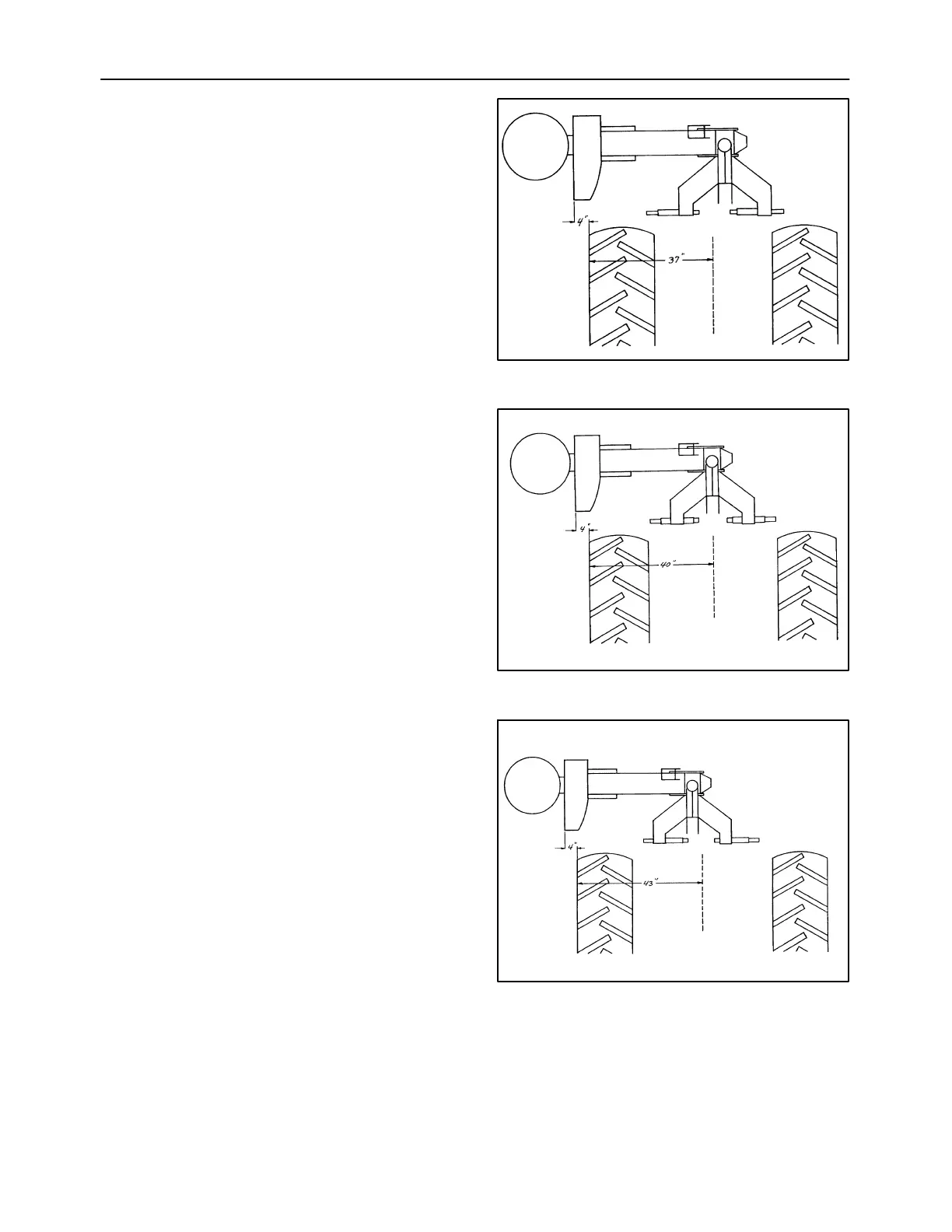
Measure from the center of the tractor to the right side
of the right tire.
For tractors that measure 940 mm (37 in) or less,
position both hitch pins to the right so that only the
round pin protrudes on the left side of the main frame
arms. This will position the mower towards the left,
moving the cutter bar closer to the right side tractor
tire.
NOTICE: The tractor lower link arms may need to be
offset slightly to the left to prevent the mower PTO
shaft from contacting the inner end of the left hitch
pin.
For tractors that measure 1016 mm (40 in), center
the hitch pins in the main frame arm.
For tractors that measure 1092 mm (43 in), position
the hitch pins to the left so that only the round pin
protrudes on the right side of the main frame arms.
This will position the mower towards the right, away
from the right side tractor tire.
NOTICE: The tractor lower link arms may need to be
offset slightly to the right to prevent the mower PTO
shaft from contacting the inner end of the right hitch
pin.
For tractors that measure more than 1092 mm (43
in), the tractor lower link arm sway bars or check
chains can be adjusted to further offset the mower to
the right, or the right side tire should be moved
inward.
NOTICE: The tractor lower links should be posi-
tioned straight behind the tractor, or have minimal off-
set. Excessive offset in either direction may cause
damage to the mower PTO drive shaft due to exces-
sive operating angles or contact with hitch pins,
and will also put “lead” or “lag” into the cutter bar
resulting in reduced cutting width and breakaway
performance.
15
16
17