SECTION 58 - DRIVELINES - CHAPTER 3
58-2
INTRODUCTION
The MD72 disc mower uses a 5 disc cutter bar to
providea6foot8inchwidthofcut.
The MD82 disc mower uses a 6 disc cutter bar to
providea7foot10inchwidthofcut.
The MD92 disc mower uses a 7 disc cutter bar to
providea9foot2inchwidthofcut.
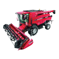
The disc cutterbar is Case IH designed and
produced, and is based on a true modular design.
Gearbox modules, 1, are connected by independent,
hardened alloy steel drive shafts, 3, running through
spacer modules, 2, and the entire cutter bar is
assembled using high strength tie bolts, 4, to clamp
the disc modules between the spacers. In the
unlikely event of catastrophic failure, damage is
contained to one module, which can be easily
replaced without disturbing other modules.
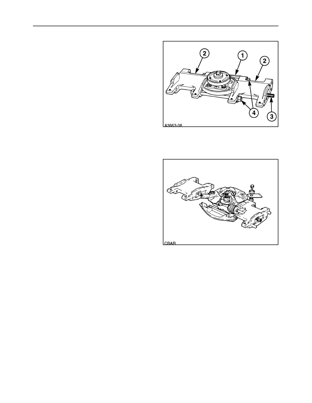
Each disc module is a separate gear case with its
own oil sump, and utilizes precision forged gears for
strength. Each module consists of a top cap
assembly and a lower module assembly.
The top cap assembly consists of the top cap
housing, a bevel gear shaft, a matched bearing set
and a disc hub. The top cap assembly can be
removed from the module for servicing, without
disassembling the cutter bar.
The lower module assembly consists of the lower
module housing and the pinion shaft and bearing
assembly. Because the pinion shaft runs at 5400
rpm, steel slingers are mounted at each end to
splash oil on the shaft seals for lubrication and
cooling.
The direction of rotation of the disc module is
determined by the installation of the pinion shaft; if
the pinion shaft is installed with the gear positioned
on the right side of the housing, the disc will rotate
clockwise. Installing the pinion shaft with the gear to
the left will rotate the disc counter-clockwise.
1
2