SERVICE MANUAL
Paragraphs 6-7
vent dirt from entering system. Place a floor jack un-
der axle main member to support axle assembly.
Remove clamp bolt (20) and nut, then thread a slide
hammer puller into end of pivot pin
(19).
Remove piv-
ot pin, then lower axle main member assembly and
remove from under tractor.
Remove tie rod and steering cylinder Remove spin-
dles if desired as outlined in paragraph 3. Inspect
bushings (17) and renew if necessary. Install new
bushings (17) and spacer (18) so that bushings are
slightly below flush with outer edges of bore in axle
main member
Reinstall by reversing removal procedure keeping
the following points in mind: When installing pivot
pin (19), flat for clamping bolts (20) must fact down-
ward. Tighten clamping bolt and nut to a torque of
80-90 ft.-lbs. (108-122
N-m).
Tighten tie rod end slot-
ted nuts to a torque of 50 ft.-lbs. (68
N-m).
Lubricate
pivot bushings with No. 2 lithium grease.
TiE RODS AND TOE-iN
to lengthen or shorten tie rod as required. Adjust
both tie rods equally. Reassemble tie rods and
recheck toe-in. Readjust if necessary.
Front wheel toe-in on all models equipped with the
nonadjustable cast axle should be 0-5/32 inch (0-4
mm).
To adjust toe-in, refer to Fig. 6 and loosen jam
nuts at each end of tube (8). One nut is left hand
thread and the other is right hand thread. Rotate
tube as required to lengthen or shorten tie rod as-
sembly. Tighten jam nuts and recheck toe-in. Read-
just if necessary.
FRONT SUPPORT
Aii Models (Two-Wheei Drive)
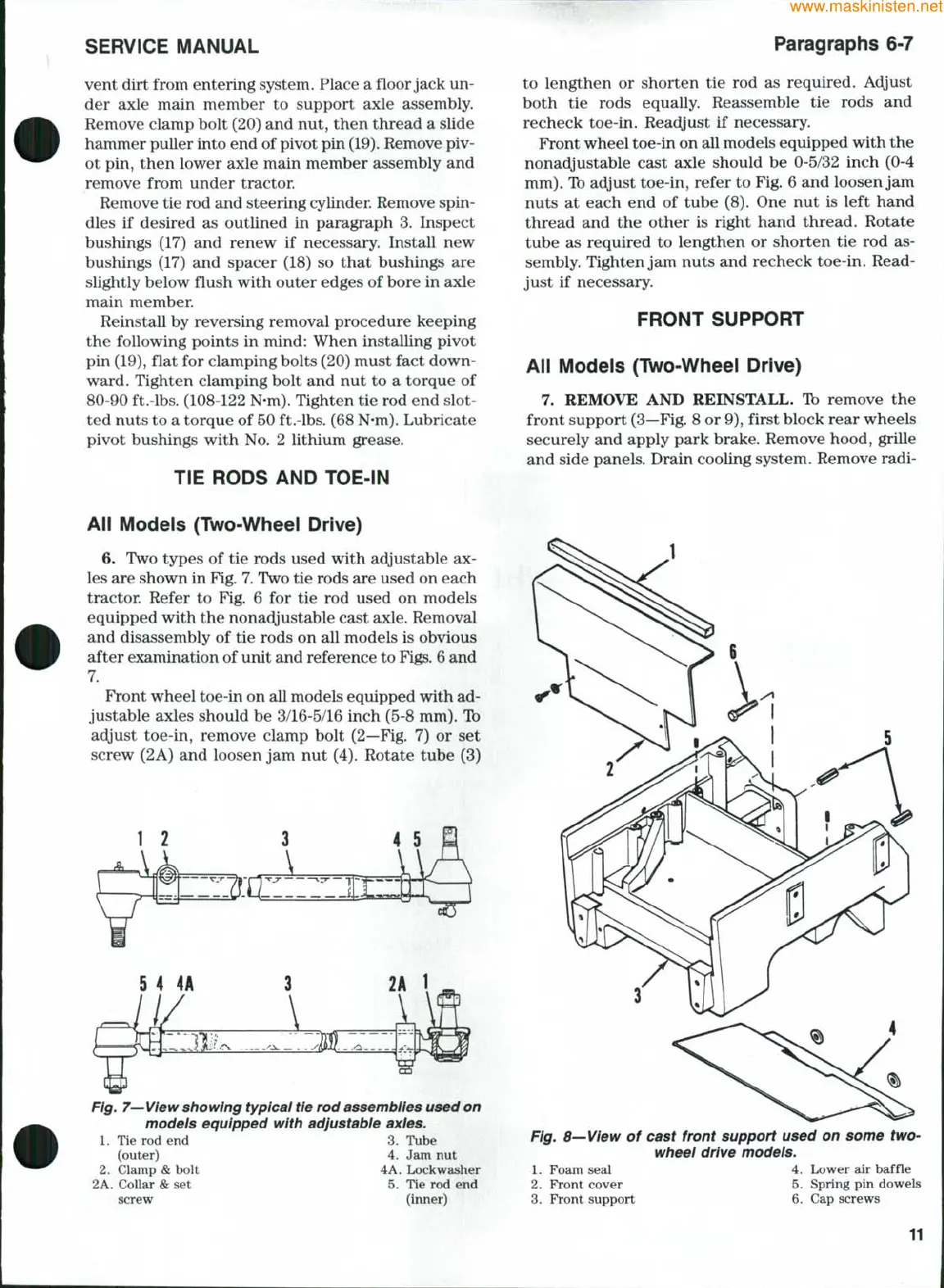
7. REMOVE AND REINSTALL. Tb remove the
front support (3—Fig. 8 or
9),
first block rear wheels
securely and apply park brake. Remove hood, grille
and side panels. Drain cooling system. Remove radi-
All Modeis (Two-Wheei Drive)
6. Two types of tie rods used with adjustable ax-
les are shown in Fig. 7. Two tie rods are used on each
tractor. Refer to Fig. 6 for tie rod used on models
equipped with the nonadjustable cast axle. Removal
and disassembly of tie rods on all models is obvious
after examination of unit and reference to
Figs.
6
and
7.
Front wheel toe-in on all models equipped with ad-
justable axles should be 3/16-5/16 inch (5-8 mm). Ib
adyust toe-in, remove clamp bolt (2—Fig. 7) or set
screw (2A) and loosen jam nut (4). Rotate tube (3)
Fig.
7—View
showing typicai tie rod assembiies used on
models equipped with adjustabie axies.
1.
Tie rod end 3. Tube
(outer) 4. Jam nut
2.
Clamp & bolt 4A
2A. Collar & set
screw
Lockwasher
5.
Tie rod end
(inner)
Fig. 8—View of cast front support used on some two-
wheei drive models.
1.
Foam seal 4. Lower air baffle
2.
Front cover 5. Spring pin dowels
3.
Front support 6. Cap screws
11
 Loading...