SERVICE MANUAL
Paragraphs 136-137
has stopped moving, stop the engine. Place a mark
on a lift arm and the hydraulic housing. Slowly turn
adjusting screw clockwise until hitch just starts to
lower, then turn the screw 3/4 turn counterclockwise.
Remove adjusting wrench and using a new gasket,
install cover plate.
UNLOADING AND FLOW CONTROL
VALVE
All Models
136.
R&R AND OVERHAUL. On models without
cab,
unbolt and remove seat. On models with cab, re-
move floor mat, seat and floor plate. Then, on all
models, clean dirt from unloading and flow valve and
surrounding area. Disconnect inlet and outlet pipes
and cap all openings. Unbolt and remove the valve
assembly and place on a clean work bench.
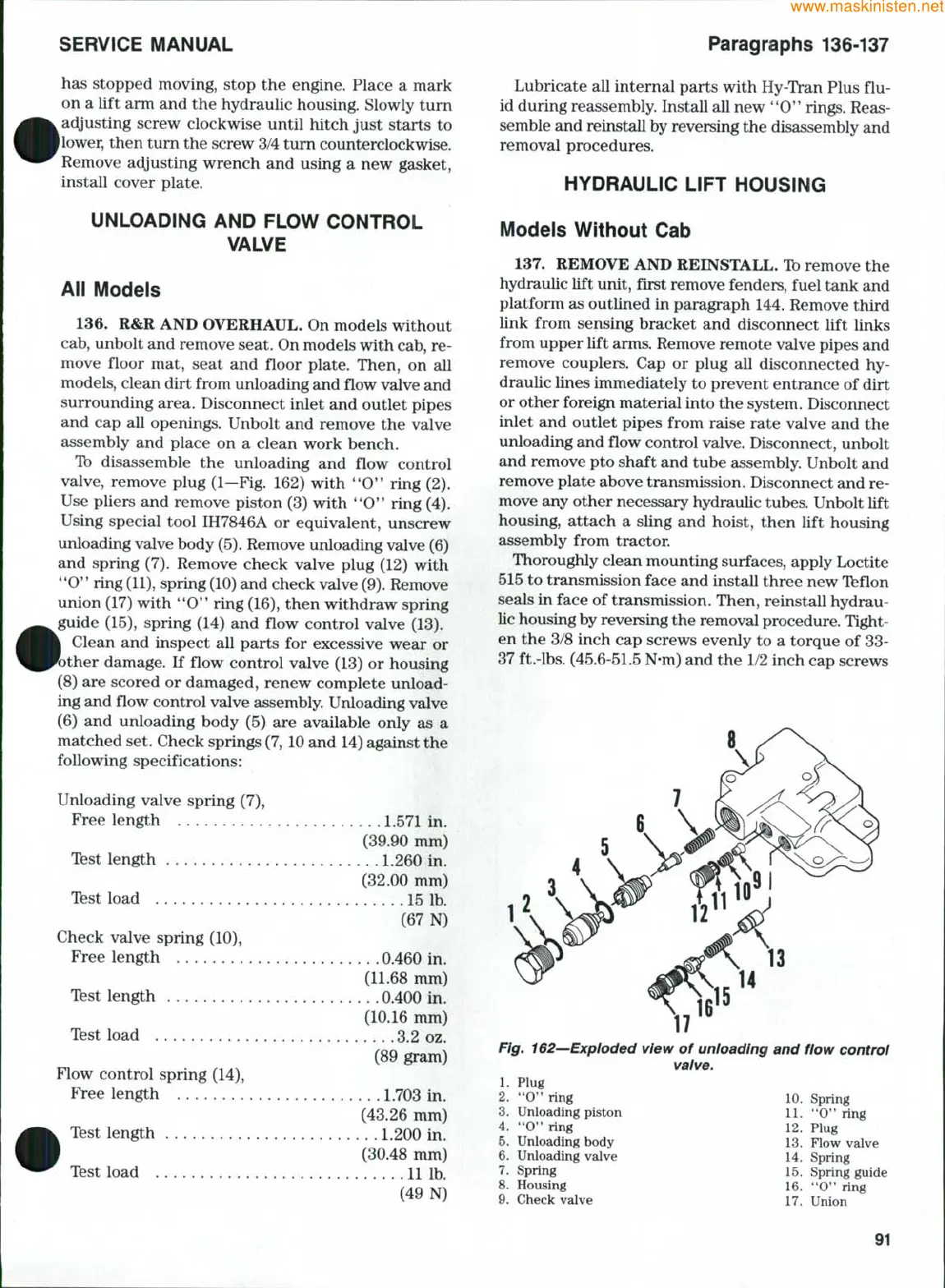
Tb disassemble the unloading and flow control
valve, remove plug (1—Fig. 162) with *'O" ring (2).
Use pliers and remove piston (3) with **0" ring (4).
Using special tool IH7846A or equivalent, unscrew
unloading valve body
(5).
Remove unloading valve (6)
and spring (7). Remove check valve plug (12) with
**0"
ring
(11),
spring
(10)
and check valve
(9).
Remove
union (17) with '*0" ring (16), then withdraw spring
guide (15), spring (14) and flow control valve (13).
Clean and inspect all parts for excessive wear or
ther damage. If flow control valve (13) or housing
(8) are scored or damaged, renew complete unload-
ing and flow control valve assembly. Unloading valve
(6) and unloading body (5) are available only as a
matched set. Check springs
(7,
10 and 14) against the
following specifications:
Unloading valve spring (7),
Free length . 1.571 in.
(39.90 mm)
Tbst length 1.260 in.
(32.00 mm)
Tfest load 15 Ib.
(67 N)
Check valve spring (10),
Free length 0.460 in.
(11.68 mm)
Tbst length 0.400 in.
(10.16 mm)
Tbst load 3.2 oz.
(89 gram)
Flow control spring (14),
Free length 1.703 in.
(43.26 mm)
Tbst length 1.200 in.
(30.48 mm)
Tbst load 11 Ib.
(49 N)
Lubricate all internal parts with Hy-Tran Plus flu-
id during reassembly. Install all new '*0" rings. Reas-
semble and reinstall by reversing the disassembly and
removal procedures.
HYDRAULIC LIFT HOUSING
Models Without Cab
137.
REMOVE AND REINSTALL. Tb remove the
hydraulic lift unit, first remove fenders, fuel tank and
platform as outlined in paragraph 144. Remove third
link from sensing bracket and disconnect lift links
from upper lift arms. Remove remote valve pipes and
remove couplers. Cap or plug all disconnected hy-
draulic lines immediately to prevent entrance of dirt
or other foreign material into the system. Disconnect
inlet and outlet pipes from raise rate valve and the
unloading and flow control valve. Disconnect, unbolt
and remove pto shaft and tube assembly. Unbolt and
remove plate above transmission. Disconnect and re-
move any other necessary hydraulic tubes. Unbolt lift
housing, attach a sling and hoist, then lift housing
assembly from tractor.
Thoroughly clean mounting surfaces, apply Loctite
515 to transmission face and install three new Tbflon
seals in face of transmission. Then, reinstall hydrau-
lic housing by reversing the removal procedure. Tight-
en the 3/8 inch cap screws evenly to a torque of 33-
37 ft.-lbs. (45.6-51.5 N-m) and the 1/2 inch cap screws
Fig. 162—Exploded view of unloading and flow control
valve.
1.
Plug
2.
'*0'* ring
3.
Unloading piston
4. **0*'
ring
5.
Unloading body
6. Unloading valve
7.
Spring
8. Housing
9. Check valve
10.
Spring
11.
**0'*
ring
Plug
Flow valve
Spring
Spring guide
12,
13
14
15
16.
**b" ring
17.
Union
91
 Loading...