SERVICE MANUAL
Paragraph 3
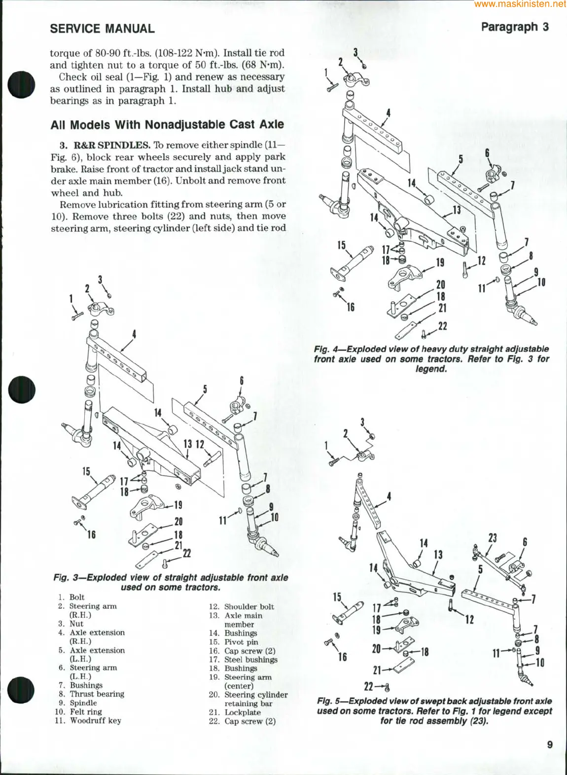
torque of 80-90 ft.-lbs. (108-122 N-m). Install tie rod
and tighten nut to a torque of 50 ft.-lbs. (68 N*m).
Check oil seal (1—Fig. 1) and renew as necessary
as outlined in paragraph 1. Install hub and ac^ust
bearings as in paragraph 1.
All Models With Nonadjustable Cast Axie
3.
R&R SPINDLES.
To
remove either spindle
(11—
Fig. 6), block rear wheels securely and apply park
brake. Raise front of tractor and install jack stand un-
der axle main member
(16).
Unbolt and remove front
wheel and hub.
Remove lubrication fitting from steering arm (5 or
10).
Remove three bolts (22) and nuts, then move
steering arm, steering cylinder (left side) and tie rod
Fig. 3^Exploded view of straight adjustable front axle
used on some tractors.
1.
Bolt
2.
Steering arm 12. Shoulder bolt
(R.H.) 13.
3.
Nut
4.
Axle extension
(R.H.)
5.
Axle extension
{L.H.)
Steering arm
(L.H.)
Bushings
Thrust bearing 20.
Spindle
6.
7.
8.
9.
10.
Felt ring
11.
Woodruff key
Axle main
member
Bushings
15.
Pivot pin
16.
Cap screw (2)
17.
Steel bushings
18.
Bushings
Steering arm
(center)
Steering cylinder
retaining bar
Lockplate
14
19
Fig. 4—Exploded view of heavy duty straight adjustable
front axle used on some tractors. Refer to Fig. 3 for
legend.
21
22.
Cap screw (2)
22-*i
Fig. 5—Exploded
view
of swept back adjustable front axle
used on some tractors. Refer to Fig. 1 for legend except
for tie rod assembly (23).
9
 Loading...