Paragraphs 8-10
CASE/INTERNATiONAL
ator as outlined in paragraph 68. Remove front axle
as outlined in paragraph 4 or 5.
On models with cast front support, disconnect up-
per steering lines. Cap or plug all openings. On all
models, unbolt and remove oil pan shield. Attach a
hoist to front support, then unbolt and remove front
support (cast support) or front support and side plate
assembly (fabricated support).
Reinstall by reversing removal procedure. Tighten
front support mounting 5/8 inch bolts to 220 ft.-lbs.
(298 N-m) torque and 3/4 inch bolts to 400 ft.-lbs. (542
N-m) torque.
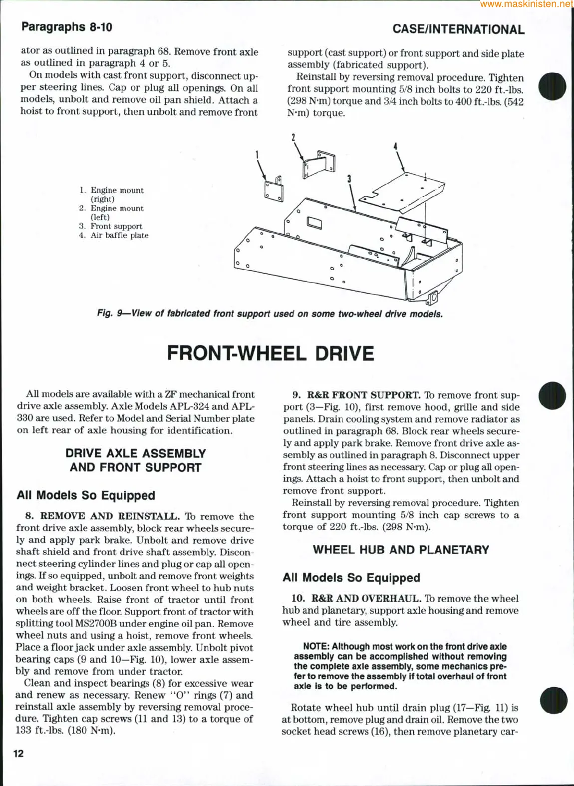
1.
Engine mount
(right)
2.
Engine mount
(left)
3.
Front support
4.
Air baffle plate
Fig. 9—View of fabricated front support used on some two-wheei drive models.
FRONT-WHEEL DRIVE
All models are available with a
ZF
mechanical front
drive axle assembly. Axle Models APL-324 and APL-
330 are used. Refer to Model and Serial Number plate
on left rear of axle housing for identification.
DRiVE AXLE ASSEMBLY
AND FRONT SUPPORT
Aii Modeis So Equipped
8. REMOVE AND REINSTALL. Ib remove the
front drive axle assembly, block rear wheels secure-
ly and apply park brake. Unbolt and remove drive
shaft shield and front drive shaft assembly. Discon-
nect steering cylinder lines and plug or cap all open-
ings.
If
so
equipped, unbolt and remove front weights
and weight bracket. Loosen front wheel to hub nuts
on both wheels. Raise front of tractor until front
wheels are off the floor Support front of tractor with
splitting tool MS2700B under engine oil pan. Remove
wheel nuts and using a hoist, remove front wheels.
Place a floor jack under axle assembly. Unbolt pivot
bearing caps (9 and 10—Fig. 10), lower axle assem-
bly and remove from under tractor.
Clean and inspect bearings (8) for excessive wear
and renew as necessary. Renew *'O" rings (7) and
reinstall axle assembly by reversing removal proce-
dure.
Tighten cap screws (11 and 13) to a torque of
133 ft.-lbs. (180 N-m).
9. R&R FRONT SUPPORT. Ib remove front sup-
port (3—Fig. 10), first remove hood, grille and side
panels. Drain cooling system and remove radiator as
outlined in paragraph 68. Block rear wheels secure-
ly and apply park brake. Remove front drive axle as-
sembly as outlined in paragraph 8. Disconnect upper
front steering lines as necessary. Cap or plug all open-
ings.
Attach a hoist to front support, then unbolt and
remove front support.
Reinstall by reversing removal procedure. Tighten
front support mounting 5/8 inch cap screws to a
torque of 220 ft.-lbs. (298 N-m).
WHEEL HUB AND PLANETARY
Aii Modeis So Equipped
10.
R&R AND OVERHAUL. Ib remove the wheel
hub and planetary, support axle housing and remove
wheel and tire assembly.
NOTE:
Aitiiough most woric on the front drive axle
assembiy can be accompiished without removing
the complete axie assembiy, some mechanics pre-
fer to remove the assembiy if totai overhaui of front
axie is to be performed.
Rotate wheel hub until drain plug (17—Fig. 11) is
at bottom, remove plug and drain
oil.
Remove the two
socket head screws (16), then remove planetary car-
12
 Loading...