STEP
41
BP9502297
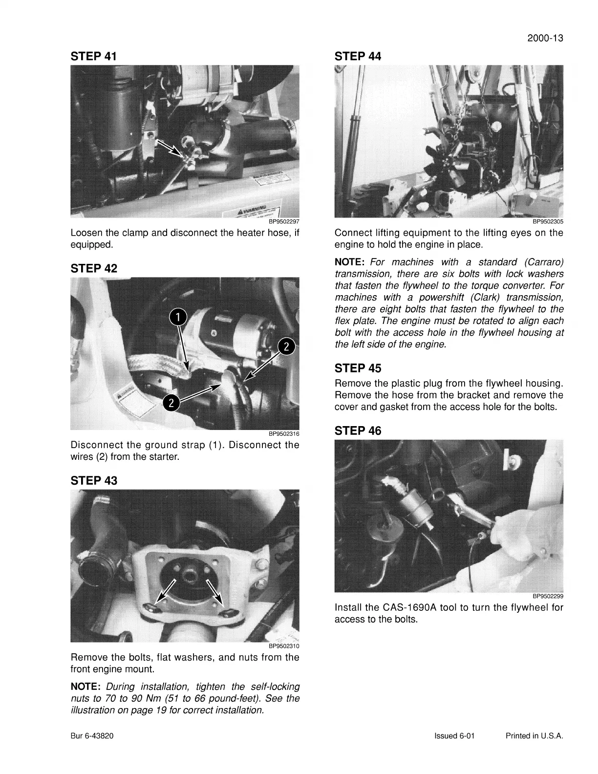
Loosen the clamp and disconnect the heater hose, if
equipped.
STEP 42
BP9502316
Disconnect
the ground strap
(1
).
Disconnect
the
wires
(2)
from the starter.
STEP 43
-:;;:",
BP9502310
Remove the bolts, flat washers, and nuts from the
front engine mount.
NOTE: During installation, tighten
the
self-locking
nuts
to
70
to
90
Nm
(51
to
66 pound-feet). See the
illustration
on
page
19
for correct installation.
Bur 6-43820
2000-13
STEP 44
BP9502305
Connect lifting equipment to the lifting eyes
on
the
engine to hold the engine
in
place.
NOTE: For machines
with
a standard (Carrara)
transmission, there are six bolts
with
lock washers
that fasten the flywheel
to
the torque converter. For
machines with a powershift (Clark) transmission,
there are eight bolts that fasten
the
flywheel
to
the
flex plate.
The
engine must be rotated
to
align each
bolt
with
the
access hole
in
the
flywheel housing at
the
left side
of
the
engine.
STEP 45
Remove the plastic plug from the flywheel housing.
Remove the hose from the bracket and remove the
cover and gasket from the access hole for the bolts.
STEP 46
BP9502299
Install the CAS-1690A tool to turn the flywheel for
access
to
the bolts.
Issued
6-01
Printed
in
U.S.A.