50 SECTION 35 - HYDRAULIC SYSTEM
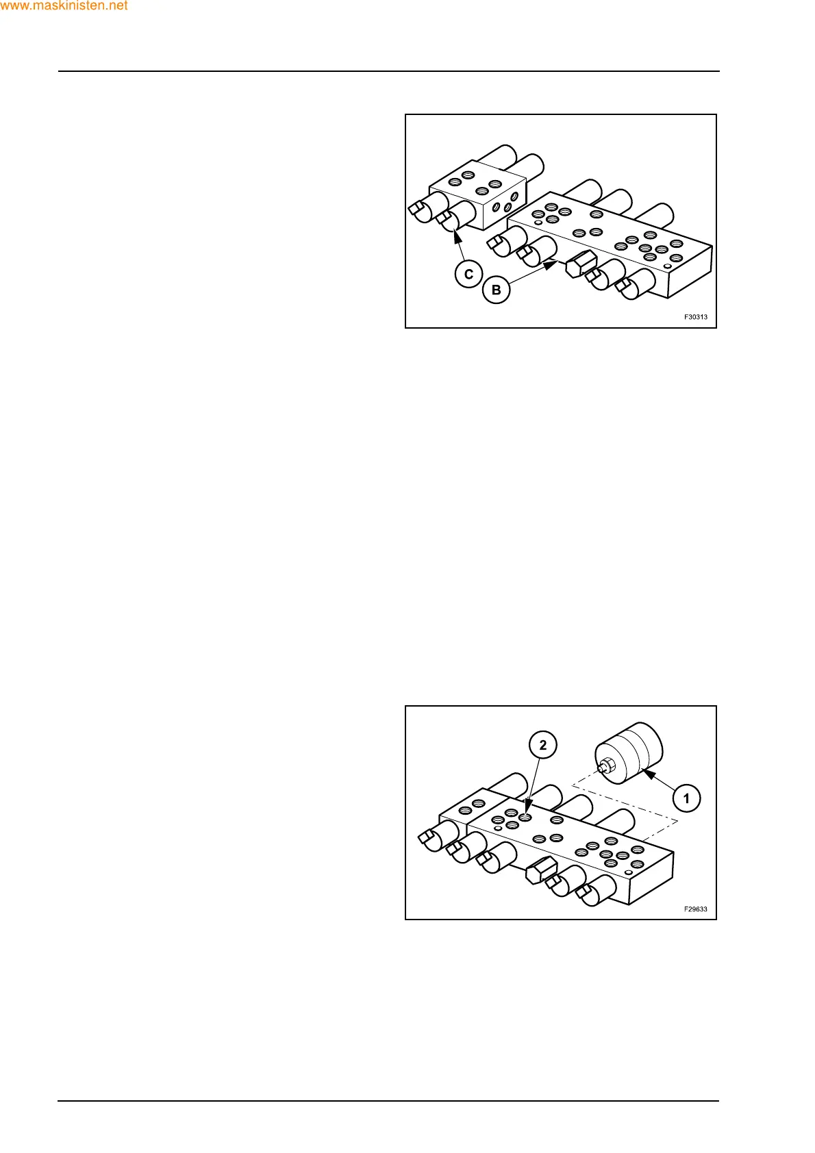
If the loader backhoe is equipped with a telescopic
dipper and if the rear control valve contains an aux-
iliary section, the solenoid valve consists of valve (B)
and module (C).
Removal
Z Position the loader backhoe on a hard level sur-
face.
Z Lower the loader attachment to the ground.
Z Lower the stabilizers.
Z Position the dipper in the vertical position, with the
bucket firmly placed on the ground.
Z Stop the engine and relieve any residual pressure
in the backhoe and loader attachment systems by
moving the relevant control levers through all oper-
ating positions.
Z Disconnect the battery.
Z Clean the area around the solenoid valve.
Z Tag and identify the position of all hoses and hy-
draulic tubes.
Z Disconnect and plug all the hoses and all the hy-
draulic tubes.
Z Unscrew and remove clamping screws to chassis
supporting the operating levers.
Z Remove the solenoid from the loader backhoe.
Z Installation is removal procedure in reverse.
Disassembly
Unscrew and remove the accumulator (1) from the
solenoid valve assy (2).