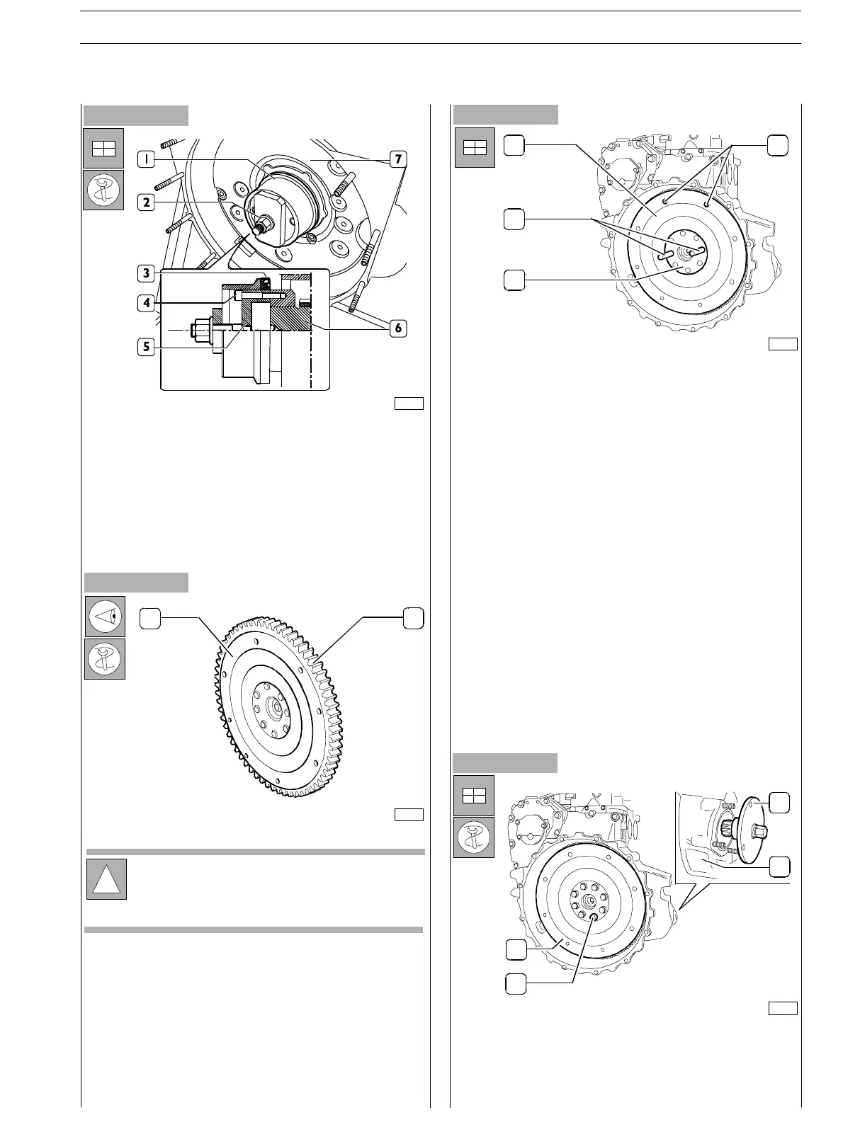
Figure 150
- Apply to engine drive shaft rear tang (6), the detail (5)
of the tool 380000666, fix it tightening the screws (4) and
key the new holding ring on it (3).
- Plac e detail (1) on detail (5), tighten the screw nut (2)
until complete assembly of the fixing ring (3) into the
flywheel cover box (7).
Figure 151
Figure 152
- Tighten the screws (4 ) f i xi ng the engine flywheel (3) to
the engine shaft. Use 380000988 tool (2) to operate on
the flywheel cover box (1) to b lock engine flywheel
rotation.
0901t
12
75696
!
In case of engine coupling with mechanical gear s in
presence of friction, verify surface status of the
flywheel and eventually work it out to maintain rated
engine flywheel thickness, which is 49,6 ± 0,13 mm.
- Check the conditions of the rim tooth (2). Whether
tooth break or excessive wear is detected, disassemble
the rim from the engine flywheel u sin g a common w illow
and replace with a new one, previously heated to
150º C degrees for 15’ ÷ 20’; seconds; bevelling must
be made towards engine flywheel direction.
1
2
3
4
75690
- Screw up two hooks or trail rings in the flywheel (1)
threaded ports (4) for handling .
- Using a hoist, handle the flywheel to place it in its housing
inside the flywheel cover box.
- Screw up to pins (2) having appropriate length, in the
shaft ports (3) and using them as guide, assemble the
engine flywheel (1) properly placing it in side the flywheel
cover box.
Figure 153
2
1
3
4
75692
SECTION 3 − DUTY − INDUSTRIAL APPLICATION E NG I NE S
51
ED. FEBUARY 2003
zs