General Specifications
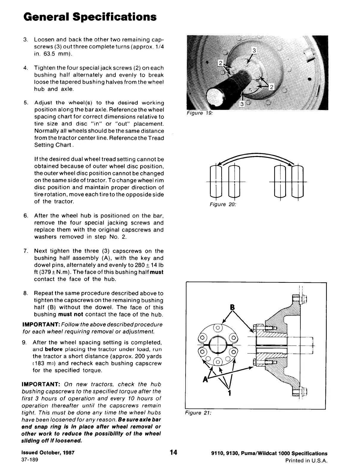
3. Loosen and back the other two remaining cap-
screws
(3)
out three complete turns (approx.
1/4
in.
63.5
mm).
4. Tighten the four special jack screws (2) on each
bushing half alternately and evenly to break
loose the tapered bushing halves from the wheel
hub and axle.
5. Adjust the wheel(s) to the desired working
position along the bar axle. Reference the wheel
spacing chart for correct dimensions relative to
tire size and disc "in" or "out" placement.
Normally all wheels should be the same distance
from the tractor center line. Reference the Tread
Setting Chart.
If the desired dual wheel tread setting cannot be
obtained because of outer wheel disc position,
the outer wheel disc position cannot be changed
on the same side of tractor. To change wheel rim
disc position and maintain proper direction of
tire rotation, move each tire to the opposide side
of the tractor.
6. After the wheel hub is positioned on the bar,
remove the four special jacking screws and
replace them with the original capscrews and
washers removed in step No. 2.
7. Next tighten the three (3) capscrews on the
bushing half assembly (A). with the key and
dowel pins, alternately and evenly to 280
±
14
lb
ft (379 ± N.m). The face of this bushing half must
contact the face of the hub.
8. Repeat the same procedure described above to
tighten the capscrews on the remaining bushing
half (B) without the dowel. The face of this
bushing must not contact the face of the hub.
IMPORTANT: Follow the above described procedure
for each wheel requiring removal or adjustment.
9. After the wheel spacing setting is completed,
and before placing the tractor under load, run
the tractor a short distance (approx. 200 yards
c183
mi) and recheck each bushing capscrew
for the specified torque.
IMPORTANT: On new tractors, check the hub
bushing capscrews to the specified torque after the
first 3 hours of operation and every 10 hours of
operation thereafter until the capscrews remain
tight. This must be done any time the wheel hubs
have been loosened for any reason.
Be sure axle bar
end snap ring Is In place after wheel removal or
other work to reduce the posslb/1/ty of the wheel
slldlng off
If
loosened.
Issued October, 1987
37-189
14
Figure 19:
Figure 20:
Figure 21:
9110, 9130, Puma/Wildcat 1000 Specifications
Printed in U.S.A.
 Loading...