5 - 15
ELECTRIC CIRCUIT
CASE TRAINING CENTER
AUGUST 2000
H/S/L mode control
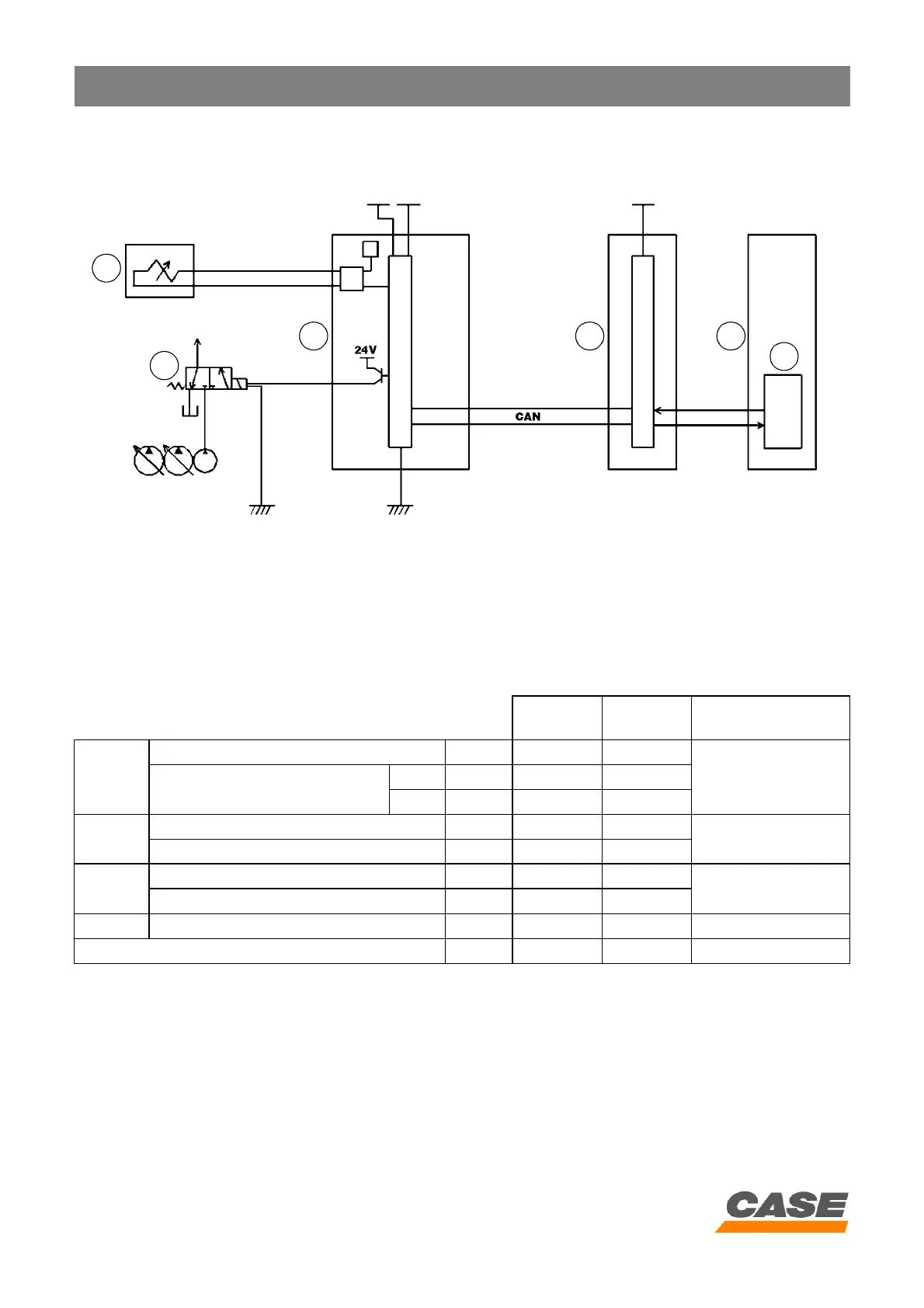
1) Circuit configuration
CS00F509
1. Proportioning valve
2. Power boost solenoid valve
3. Main electronic control box
4. Engine electronic control box
5. Engine
6. Electronic acceleration
2) Values set for each mode
NOTE: The shown above are for normal conditions; the following are exceptions:
1. If the target number of engine revolutions is less than the maximum torque number of revolutions, the pump is
controlled by the value of "L" mode current (even in H/S modes)
2. In "L" mode, if travel operation only is actuated, the pump is controlled by the value of "S" mode current
3. In "L" mode, if a hydraulic hammer or grab is used, the pump is controlled by the value of "S" mode current.
4. If the engine coolant solution temperature is too low, or the voltage arriving at the engine electronic control box is
too low, the idle speed increases to prevent the engine becoming too cool or the battery being discharged.
CX130 CX210
Hydraulic power
boost
Mode H
Number of engine revolutions (Maxi) rpm 2150±10 2000±10
Automatic control
Current (variable amperage)
(Max) mA 600 407
(Min) mA 450 292
Mode S
Number of engine revolutions (Max -200) rpm 1950±10 1800±10
Automatic control
Fixed current amperage (90% of torque) mA 450 292
Mode L
Number of engine revolutions (Max -300) rpm 1850±10 1700±10
Constant
Fixed current amperage (70% of torque) mA <100 <50
Idle Number of engine revolutions rpm 1000±10 900±10 -----
Number of engine revolutions at maximum torque rpm 1600 1600 -----
1
2
3 4 5
6