ELECTRIC CIRCUIT
5 - 16
CASE TRAINING CENTER
AUGUST 2000
Automatic mode control
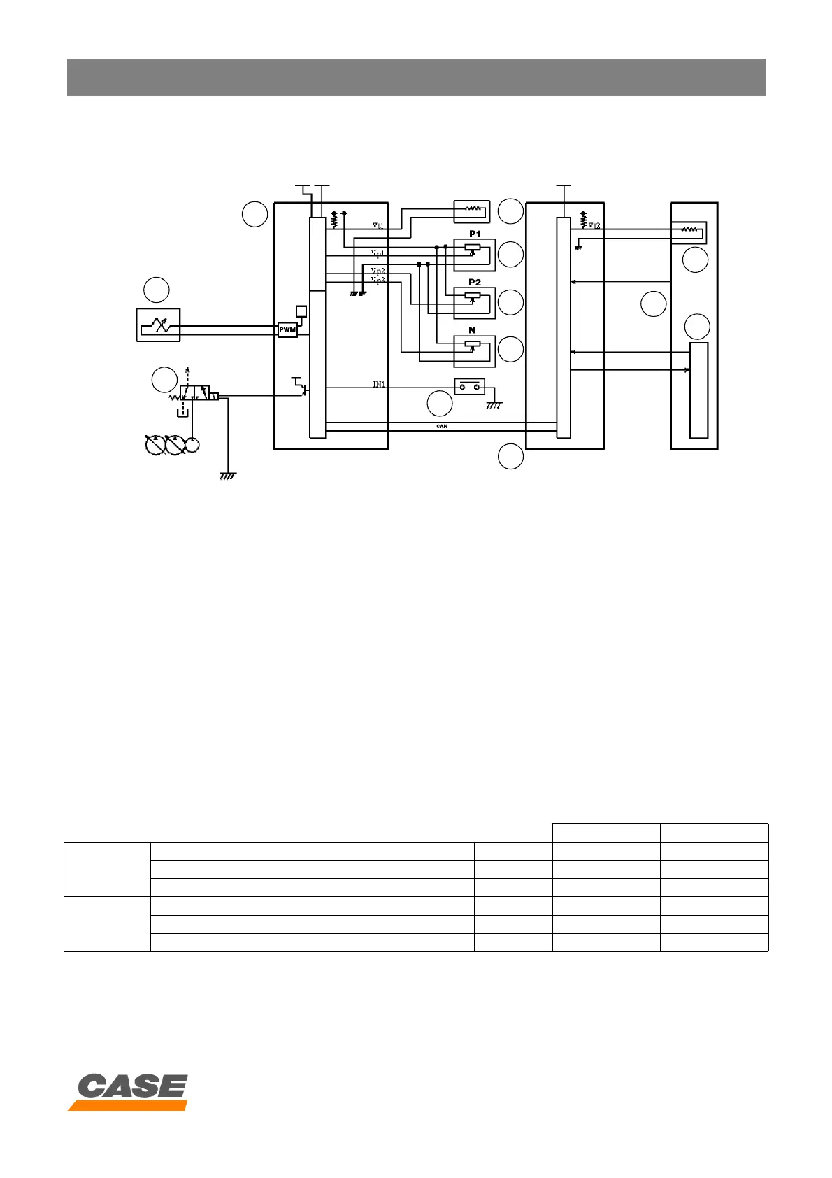
1) Circuit configuration
CS00F510
1. Proportioning valve
2. Power boost solenoid valve
3. Main electronic control box
4. Hydraulic oil temperature sender
5. Pressure detector P1
6. Pressure detector P2
7. Hydraulic pump regulating detector (N)
8. Travel pilot pressure switch
9. Engine electronic control box
10. Engine
11. Electronic acceleration
12. Water temperature sender
2) Description
1. If auto mode is selected, 2 modes, SA and LA, are
available.
2. When auto mode is selected, L
A mode is engaged,
which then automatically changes to S
A or LA
depending on working conditions.
3. If the engine coolant solution temperature is below
50°C or the oil temperature below 25°C, auto mode
control does not operate and L
A mode is selected.
When the water temperature is above 50°C and the
oil temperature above 25°C, auto mode starts and
continues operating even if the water and oil
temperatures fall.
4. When auto mode control is operating, if the travel
pressure switch (8) is operated, the mode change
does not take place. (If the travel pressure switch is
operated in S
A mode, the system stays in SA mode
and if the pressure switch is operated in LA mode, the
system stays in L
A mode).
1
2
3
4
5
6
7
8
9
10
11
12
CX130 CX210
SA mode
Number of engine revolutions (MAX) rpm 1950±10 1800±10
Current (equal to S mode + 40 mA) mA 490 332
Hydraulic power boost --- Automatic Automatic
LA mode
Number of engine revolutions (MAX) rpm 1850±10 1700±10
Current (equal to S mode) mA 450 292
Hydraulic power boost --- Automatic Automatic