5 - 33
ELECTRIC CIRCUIT
CASE TRAINING CENTER
AUGUST 2000
Locking functions
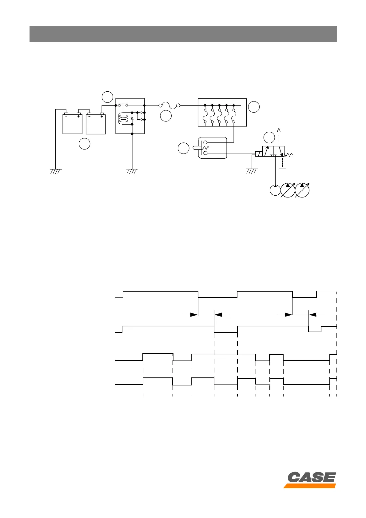
1) Circuit configuration
CS00F501
1. Battery
2. Battery relay
3. Main protective fuse
4. Fuse box
5. Control cancellation lever switch
6. Pilot pressure control solenoid valve
2) Timing diagram
3) Operation
When the engine is started and the control cancellation lever is in the work position, the pilot pressure solenoid
valve is activated.
When the pilot pressure solenoid valve is activated, the pilot pressure is supplied to the pilot systems and the
machine is ready to operate.
1
2
3
4
5
6
3 sec
3 sec
24 V
Starter motor switch
ON
ON
0 V
OFF
OFF
ON
OFF
Supply
Control cancellation lever
position
Pilot pressure solenoid
valve