ELECTRIC CIRCUIT
5 - 34
CASE TRAINING CENTER
AUGUST 2000
Power boost
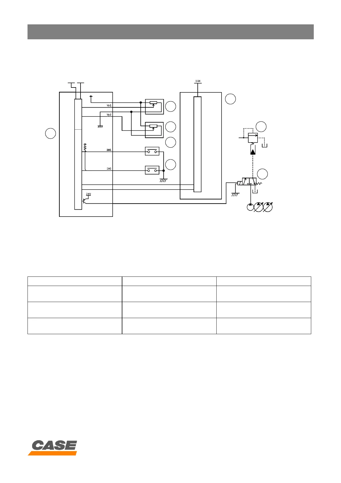
1) Circuit configuration
CS00F502
1. Main electronic control box
2. Pressure detector P1
3. Pressure detector P2
4. Travel pilot pressure switch
5. Option pilot pressure switch
6. Engine electronic control box
7. Main valve
8. Power boost solenoid valve
2) Pressure increase in each work mode
* When the travel or option pressure switch is activated, the power boost is deactivated.
3) Operation
When operating in mode H or S, the main electronic
control box (1) registers the ratio between:
- The load on the engine transmitted by the engine
electronic control box (6).
- The load on the hydraulic system transmitted by
the pressure detectors P1/P2 (2 and 3).
If pressure P1 or P2 is higher than 300 bar (30 MPa)
and the load ratio remains within a range of ± 5% for 2
seconds, the main electronic control box (1) activates
the power boost solenoid valve (8) for 8 seconds
which increases the main pressure.
When the travel (4) or option (5) pressure switch is
activated, the main electronic control box deactivates
the power boost solenoid valve.
2
5
6
3
4
7
8
1
CX130 CX210
Mode H
(Pressure)
Automatic power boost (*)
(34.3 « 36.3 MPa)
Automatic power boost (*)
(34.3 « 37.3 MPa)
Mode S
(Pressure)
Automatic power boost (*)
(34.3 « 36.3 MPa)
Automatic power boost (*)
(34.3 « 37.3 MPa)
Mode L
(Pressure)
Constant power boost (*)
(36.3 MPa)
Constant power boost (*)
(37.3 MPa)